filmov
tv
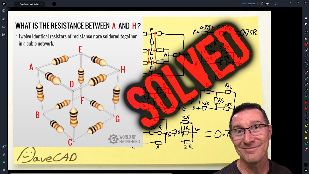
EEVblog 1472 - Resistor Cube Problem SOLVED
Показать описание
How to solve the resistor cube problem using equipotential nodes, short and open techniques, and circuit simplification.
00:00 - The Resistor Cube problem
04:28 - The SECRET to circuit simplification using equipotential nodes
06:04 - Analysis "by inspection"
14:22 - Summary of the solution
16:14 - Let's BUILD it!
19:28 - Two resistors are entirely redundant!
Support the EEVblog on:
Buy anything through that link and Dave gets a commission at no cost to you.
Donate With Bitcoin & Other Crypto Currencies!
#ElectronicsCreators #Tutorial
 0:19:56
EEVblog 1472 - Resistor Cube Problem SOLVED
 0:23:27
EEVblog 1474 - Can You Measure Capacitors IN Circuit?
 0:19:43
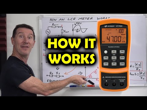
EEVblog 1473 - How Your LCR Meter Works
 0:18:52
EEVblog 1482 - Mains Capacitor Zener Regulator Circuit
 0:23:27
EEVblog 1401 - DC Power, Efficiency, & Maximum Power Transfer Theory
 0:17:06
EEVblog 1485 - PedalCell CadenceX Bike Generator LOL FAIL!
 0:19:46
eevBLAB 97 - Is Apple Serious About Right To Repair? (The Verge)
 0:29:37
EEVblog 1422 - CAUSE of the Tesla Victoria Big Battery Fire
 0:27:02
EEVblog 1481 - Dodgy Dangerous Heater REPAIR
 0:29:45
EEVblog 1475 - What's This SMD Part?
 0:28:34
EEVblog 1452 - Fluke PM3370B Combiscope REPAIR
 0:28:38
EEVblog 1427 - An INFURIATING Electronics Exam Question!
 0:37:32
EEVblog 1471 - Mailbag
 0:00:46
Resistor Cube Problem
 0:07:11
eevBLAB 98 - The Pressure Youtubers Are Under
 0:58:25
EEVblog 1461 - The MOSFET Search CHALLENGE
 0:24:28
EEVblog 1470 - AC Basics Tutorial Part 3 - Complex Numbers are EASY!
 0:13:18
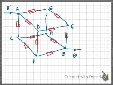
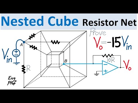
Double Cube Resistor Network with Op Amp
 0:09:45
Petition - Australian Standards Should be FREE
 0:12:32
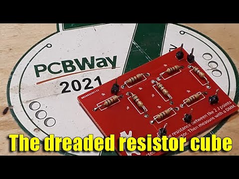
STEM BOARDS: Resistor Cube
 2:27:49
EEVblog LIVE May 14th 2022
 0:29:52
EEVblog 1486 - What you DIDN'T KNOW About Film Capacitor FAILURES!
 0:54:10
WiGL Wireless Power BUSTED AGAIN!
 0:04:54
SHORTCUT METHOD TO FIND CUBE RESISTANCE
Комментарии