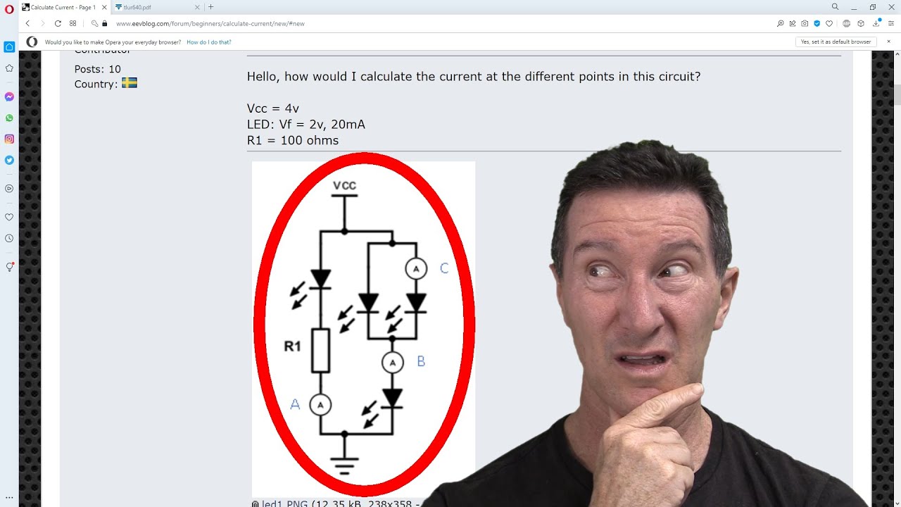
EEVblog 1427 - An INFURIATING Electronics Exam Question!

preview_player
Показать описание
From the EEVblog forum, an infuriating electronics exam question!
Plus a bonus job interview tip.

00:00 - The Forum question
02:12 - Is this a good job interview question?
03:36 - Dave's working...
07:04 - The Solution
08:08 - Other forum responses
11:40 - Kirchoff's Current Law MUST Hold!
12:51 - REBEL against The System!
15:10 - Xrunner's practical test
21:38 - Practical Test

Buy anything through that link and Dave gets a commission at no cost to you.

Donate With Bitcoin & Other Crypto Currencies!

#ElectronicsCreators
Рекомендации по теме
Комментарии
Автор

There is a reply from the OP:
"Thank you, everyone. Especially Dave for even making a whole video regarding the problem. Very interesting to read your different approaches.

So, the backstory of the problem. The circuit got handed to us in a high school entry course in electronics. The circuit was supposedly made by our teacher. Our teacher seems to have lacking knowledge regarding LEDs and current in a series circuit. By his means, the LED drops voltage AND current. I had to prove him wrong 8).

We got to both calculate and elaborate. When elaborating, I got similar results as Dave in his video. But when I had to calculate the right branch, things got a little confusing, thus creating the thread. The circuit that stood out to me as my first thought was that insufficient information was given. But I made the assumption that Vf = 2.0 at all given currents(which would not be the case in reality). My conclusion was, half of the current goes through each LED which is in pairs. But the circuit seemed odd anyway.

I see some of you made some good realistic calculations, but it is not near the level of this course. Ohms law and Kirchoff's are pretty much the only formulas used. If my teacher is watching this thread, maybe he could post the sole purpose of this circuit with calculations included. The circuit in my opinion is just a brain itch and would never be used in reality(hopefully). An LED circuit is never seen as a theoretical circuit for me."

EEVblog
Автор

The only correct answer is A = 20mA, B=C=0mA because that LED no longer has any magic smoke in it.

BogdanTheGeek
Автор

I’ll never forget in the first assignment of my electronics degree I was asked to find a suitable value power resistor to limit the current in an LED in a big, convoluted yet massively oversimplified circuit of a solar panel directly charging a battery (zero protection).

Of course the LED was of the magical 3.65 V ideal type so, instead of doing a big massive current analysis for all of the insignificant wire resistances and unrelated circuit branches they gave I assumed ideal wires and just used the voltage of the power source (an ideal constant voltage battery) and a single ohms law calculation to get the value of 12 Ω, a nice E12 value.

But of course I was marked wrong for not solving it ‘correctly’ with three pages of working to get exactly 11.908 Ω.

From there I realised that the electronics class I was doing was actually just an electronics themed math class detached from any concept of practicality.

There were plenty more massively over simplified circuits in that class. I really do agree that those questions are “pathological” and should be avoided as I have had a number of people who should know better ask how I’m running a 3.3 V white/blue diode off a 3.3 or 3.0 V supply.

WizardTim
Автор

Entry-level hobbiest here and having you analyze questions like this is very satisfying. I get to think my thoughts and then learn the truth! Thanks!!!!

whiskyguzzler
Автор

Dave muttering to himself: "Right, that's question 1 done. Question 2..."
Examiner: "Okay, pens down please."

AintBigAintClever
Автор

I got this question in an interview and ended up getting arrested for assault, under the instructions of Dave I let them have it. I didn't get the job.

MrMaxeemum
Автор

A is easy. B and C you would need a characteristic curve to solve.

wouldntyouliketoknow
Автор

Answering test questions like this is an entirely different skill than real-world applications, mostly about understanding the answer they're looking for and assumptions they're making.

rdwatson
Автор

I love this problem! This is a classic Analog IC design question. The intuitive understanding of semiconductor junctions give s a quick answer to this problem. Because the nature of the junction is logarithmic, the two parallel diodes (LEDs) will have a decreased drive exactly cancelling the increased drive to the bottom single diode (LED), a ~30mA current will result in the second path due to the 1.5X effective junction area spread over the 3 diodes in the second path. The kT/q ln I1/I2 is typically18mV for a diode at room temperature, so for a small signal analysis for the LEDs, the same relationship should hold true. I am a former Analog IC designer and Analog guys LOVE the nature of logging characteristic of diodes, using them in multiplying, RMS, logging and other current mirror applications in designing ICs.

thehobe
Автор

I went through the Tomorokoshi's calculations and everything I can say about that is that they are perfectly correct and IMO it is the only correct answer to that question. It's a little bit "speedy" to me, there is no explained how the (3.1) equation was obtained from (1.3), but I didn't have to take a paper and pencil to prove it is correct, so on the other hand, it is not so hard. If you look at the (1.3) equation, there are a lot of variables, but according to (1.1) and (1.2), the η and Vt are constants, because that diodes are the same, they are only at different points of its V-A characteristics, so only the V and I varies. At the next step (1.3) was splitted to two equations with Vb Ib and Vc Ic, the rest variables was untouched because they are constants and that equations was substracted one by another which resulted in (3.1) equation. The rest is simple and easy to understand.

In my opinion, this is much beter question than something like "write the Ideal Diode Equation", because this proves that student is capable of using that equation. In fact, I have no experiences in teaching, but it looks like a good idea to me. Maybe someone experienced in teaching (like @TheSignalPath :3 ) could tell us whether exam questions like this are good or bad idea.

NikiBretschneider
Автор

I found I learned more from the 'bad circuit' ideas in the early versions of Horowitz & Hill than i did from many other texts

chizzt
Автор

The question "How would I calculate ..." appears to provide a philosophical opportunity! First, I'd power up this circuit to let the magic smoke out of that right side of the circuit. Once the smoke had cleared, the answer on the left branch of the circuit would be 20mA and the answers on the left would be a peaceful ZERO. I would choose to ignore the temporary and catastrophic vaporization of material on the right side and only consider this calculation after this circuit was at steady state. It's akin to ignoring what occurred in our Universe during its first few moments before baryonic matter condensed and only pondering life after photons were able to be emitted from these Universal LEDs.

quantumbemusement
Автор

At a job interview once, I was given a multiple choice test they had ‘borrowed’ from Microsoft where one of the questions famously had the wrong answer...

...what did I do?...

...I was congratulated for being their first candidate to ever get 100% 🤣

(I’ve felt vaguely unclean ever since).

fredbloggs
Автор

At a job interview for a proof-reader/editor position at a CD-ROM publishing company, I was given a written exam with nonsense questions, so I proof-read and corrected their exam paper...

...I didn’t get the job!

Some people have no sense of humour ☹️

fredbloggs
Автор

I don't understand why people seem to think the problem is not suitable for hand calculation or not solvable without knowing the LED specs, because a hand calculation works fine for a decent estimate (assuming matched LEDs), and isn't even difficult.

Assuming that the LEDs follow the familiar Shockley diode equation, the I-V relation is I = I0*exp((V - V0)/(n*VT)), where I0 = 20 mA and V0 = 2 V. If the voltage of the center node is 2V + Delta, KCL applied at that node gives 2*I0*exp(-Delta/(n*VT)) = I0*exp(Delta/(n*VT)), or exp(Delta/(n*VT)) = sqrt(2). The current through the bottom LED is then sqrt(2)*I0 = 28.3 mA, and the current through the upper two LEDs is half that: 14.1 mA.

Pukkeh
Автор

Kirchoff's current law is litterally the first law you learn after Ohm's law....

muppetpaster
Автор

I had an old school EE prof for my first circuits class. Had him in just about the last term before he went emeritus. He was very practical. He would say that if you couldn't understand whether the answer your calculator had given you was reasonable or not, it wasn't worth the electrons used to calculate it. I'm pretty sure this question would send him into an apoplectic fit.

briancox
Автор

The only answer that can be given from the stated data is:
A: 20mA
B: >20mA and equal to 2xC
C: <20mA

For anything better a datasheet for the diode is needed.
Building the circuit and measuring it with a unspecified ammeter cannot be used, the problem do not specify the impedance of the meter.

henrikjensen
Автор

Diodes obey Ebers-Moll: I(V)~I0 exp(V/V_T) and V=V_T ln(I/I0) where V_T=kT/q. The left side does balance; since (100)(0.02)=2V, point A is at 2V at 20mA so the LED voltage is 2V at 20mA... this is the given point. But the right side does not balance. Since I_B=2I_C, we can find the difference between the two LED voltages:
V_B-V_C=V_T [ln(I_B/I0) - ln(I_C/I0)] =V_T ln(I_B/I_C) = V_T ln(2) Kirchoff's loop also gives
V_B+V_C=4V Adding these we see
2V_B=4V+V_T ln(2) and V_B=2V + V_T ln(2)/2 The node voltage is elevated...
Now, use V_B-2V=V_T [ln(I_B/I0) - ln(20 mA/I0) = V_T ln(I_B/20 mA) Combine these
V_T ln(I_B/20 mA) = V_B-2V = [2V + V_T ln(2)/2] - 2V = V_T ln(2)/2 Cancel V_T to see
I_B = 20 mA * sqrt(2) = 28.3 mA
Identical diodes will divide this current equally so that I_C=14.1 mA.

Without Ebers-Moll there would be no current mirrors, no log amps, no band gap references, etc. So it is NOT a silly question although small fluctuations will indeed be amplified in the real world. I0 and V_T are TINY, so any ammeter voltage will reduce the current significantly. This, in fact, is what causes the fluctuations to be amplified.

byronwatkins
Автор

Had what I think was a question like this in my physics final. The problem with letting them have it in the answer is that it's usually some postgrad working from an answer sheet that's marking it and they won't care or be able to do anything about it. Spend the time improving your answers on other quesitons.

chaos.corner