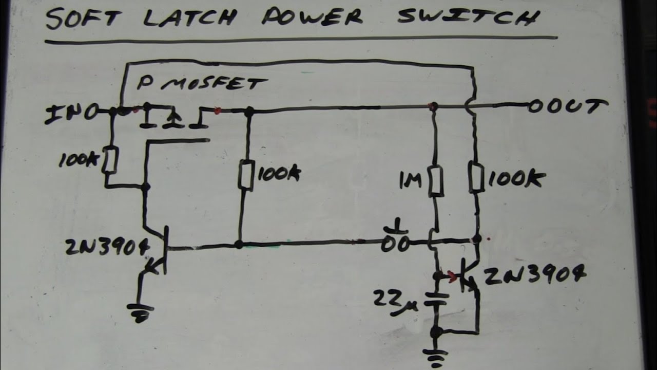
EEVblog #262 - World's Simplest Soft Latching Power Switch Circuit

preview_player
Показать описание
Want to use a single cheap momentary action push button switch to toggle your circuit power on and off? Try this circuit on for size.
Рекомендации по теме
Комментарии
Автор

FYI for those novice, such as myself, who are building this soft latching switch. I had been working on making this switch work for over a month. I'm using all bjts. I tried different resistors, different capacitors, and different types of bjts. I could not get it to latch off. As soon as I let off the momentary switch the light came back on. Holding down the push button I could get it to flash like Dave's but it would not stay in the off position. Finally I went back to original components and then it dawned on me, after viewing Dave's video a couple of dozen times, the LED I was using was not a sufficient load. I put in a 1/2 watt 2200 ohm in parallel with the LED and viola! It's working! Thanks Dave.

mathewk
Автор

Just in case you were wondering how much this saves... I got a parts list for what he drew whipped up in digikey, and this is what I found:

3A toggle switch = $1.76/unit at 200 item price break (min quantity)
200 units = *$352 total*

I will assume the 200 unit price break for the rest of these numbers and surface mount components except for the push button. If the minimum quantity is higher, I'll include that cost.
5, 000 100k resistors = $6.46 (4, 400 not used)
250 1M resistors = $7.99 (50 not used)
200 22uF capacitors = $16.86
200 30V 3.8A P-channel MOSFET's = $35.00
200 Dual NPN transistors (2 transistors, one package) = $25.90
200 Through hole momentary push buttons = $15.18
Total price = *$107.39*

Less than 1/3 the price! And I didn't even try to make things better by trying to minimize the number of different parts.

LazerLord
Автор

EEVblog Please do more videos like this, showing how circuits are developed, I learnt so much from it. I like it,

MostFolkCallMeOrangeJoe
Автор

Hi Dave, I have a slight improvement on the circuit, move the capacitor to collector of the T2 and remove 1 M resister from base of T2, connect both bases togater and put switch between the collector of t2 and basses. replace 100 k resister with 650k at collector of t2 and vcc.works just fine, no more ocilations, hold the switch as long as you want

shamsheralamraja
Автор

For anyone wanting to simulate or build some of these circuits as Dave goes along, remember that BJT transistors realistically require either a pull-up or pull-down resistor in order to ensure their default state. For example, in this video, at minute 4:00, this circuit would likely actually start in the ON condition without pressing anything because the base of Q1 (the PNP) transistor is not guaranteed to be held high, and is likely close enough to ground, it will start conducting, causing Q2 to fire turning the circuit on. If we use 100K-Ohm resistors everywhere to keep current low on the base of the BJTs, a weaker pull-up is necessary on Q1 simply to ensure the base is high on startup but can be easily overcome by the ON switch, grounding the base. For this pull-up, simply connect a 1M-Ohm resistor between the collector of Q2 and the emitter of Q1.

ReactanceIsFutile
Автор

Your channel is damn good. The way you describe things from simple to complex can rival the best tech school teacher out there. I am learning things I've never bothered to learn, all thanx to your channel. Cheers.

ddandrews
Автор

It's a really good idea! Thank you!
Remarks:
1) for the second transistor use a NMOS --> no big capacitors needed
2) use a resistor from basis to ground for the first transistor - helps against leakage current
3) If the battery voltage is more than 15V ... 20V, most of the PMOS don't like this and go to the semiconductor heaven.

gernoteyssler
Автор

Yes, it will usually be cheaper, cost it out yourself.
It's not just about cost either. Sometimes you want/need a soft switch instead of a big clunker mechanical toggle.

EEVblog
Автор

Congrats man, your video is now offered as a first result when looking for a soft on/off circuitry.
This must mean something.

evgenysavelev
Автор

your explanation with green ink makes it far more clear. clearly you prioritized how to think comprehensively. salute to you.
cheers from Indonesia

iblesbosuok
Автор

13:37

"My product never has bugs. It just develops random features."

CuentaSpam
Автор

Bread Board Success: I built Dave's circuit and it worked.
Things to note:
- I used a 5Vsupply.
- I used an IRF9Z24N P-MFET.
- I used a 47uF e-cap. Dave spec'd 22uF, but actually used a 47uF on his board. I like the button press timing of the 47uF better.
- I used a red, SMD LED with a 1K resistor, for the load.
- Dave's circuit starts in an on state, when power is first applied. To me, this is a problem. Say this is on a stereo and the power goes off/on in the night. The stereo is going to startle you awake . However, for whatever reason, mine does not start in the on state.
Lot's of fun, Mr. Dave = Thanks!

td
Автор

Living in the US I had never heard the phrase "half a bee's dick" before. I burst out laughing. Thanks Dave!

tuxthemagicpenguin
Автор

And here I was trying to find a reasonable price for a switch that could handle 200 mA and wasn't momentary...

I should ask for them to rescind my degree for the amount of time I've spent on this! It's almost like I could've saved precious time by watching every video from this channel!

Beauty!

JKnoscope
Автор

Dave, as always your tutorials are the best around! Your videos have taught me more than many of my electrical engineering classes. Thank you!

BobD
Автор

Commenting again because this is that good. This is the first video by EEVblog I've watched, but communicating the thought/development process of a circuit is what I've been searching for since my undergrad years! Extremely impressed. And delivered with an Australian (?) accent? Amazeballs, and Bob's your uncle.

kmuns
Автор

I tried the circuit @04:00 with BJTs, but without the buttons. On 'out' I had a resistor followed by a lit LED. In theory it was supposed to be off. Apparently, there's a thing called 'transistor leakage'. It means even when a transistor is in cut-off state, some current might still go through (micro-Amps in magnitude, I guess it varies among the different types). I suppose it could be ignored if applied to load, but when it's connected to a base of another transistor - it gets amplified, then it feeds the first transistor and we end up with fully activated circuit. I hope this comment will save people about half a day of puzzled head scratching. In the end it was fun to find that out, probably I should have added a "Spoiler alert" in the beginning :)

trunovmichael
Автор

Bob IS my uncle. First time I heard you say that it kind of freaked me out. I had never heard that phrase until I started watching your AMAZING videos. Thank you for all the great information and for the care you take in presenting it.

sachiperez
Автор

Important: if you have a capacitor on the output, the comportment becomes erratic. It will not latch off anymore (will turn off only while switch is closed), and oscillation becomes unbalanced.

victordss
Автор

What an explanation, watching similar video on another channel which was made 9 years after yours but I must say, your explanation is at par.

SandeepSandhu
welcome to shbcf.ru