filmov
tv
Lead, lag, and PID compensator structures using bode plots |Using Bode Plots, Part 4

Показать описание
Learn frequency domain characteristics of lead, lag, and PID controllers in this MATLAB® Tech Talk by Carlos Osorio.
 0:11:00
What are Lead Lag Compensators? An Introduction.
 0:04:43
Lead, lag, and PID compensator structures using bode plots |Using Bode Plots, Part 4
 0:28:48
Example: Design Lead-Lag Controller
 0:13:58
Designing a Lead Compensator with Root Locus
 0:33:48
Lead - Lag Compensators and PID Controllers
 0:14:19
Designing a Lead Compensator with Bode Plot
 0:04:42
Introduction to Compensator
 0:33:00
Example: Design PID Controller
 0:12:40
Comparison of P, PI, PD and PID controllers and lead and lag compensators, 13/4/2015
 0:11:58
Recap: Controller Design
 0:07:23
Lead compensator using root locus
 0:39:10
PID controller & lead-lag compensator design
 0:20:29
Lead Lag Controller
 0:04:51
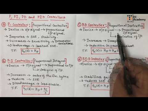
#182 P, PI, PD, PID controllers || EC Academy
 0:08:16
First-Order Lead Lag Systems
 0:00:45
Lead Lag Boiler Configuration - Autoflame Total Boiler Room Controls
 0:05:05
Lead Lag Compensator Using Sisotool
 0:21:04
Design and Implementation of Controllers using Matlab | SisoTool | Compensators | Control Systems
 0:05:03
Different Types of Controllers/ Compensators ||PI/PD/PID|| ||Lead/Lag/Lag-Lead|| ||GATE||ESE||
 0:02:36
Effects of Lead Compensator
 0:10:25
Lag Lead Compensator
 1:14:42
Lecture 20: PID and Lag-Lead Compensator Design using Root Locus
 0:02:52
Bard MC Series Lead/Lag Controller Overview
 0:53:03
Root Locus Lead Compensator Design Example (pole/zero cancellation)
Комментарии