filmov
tv
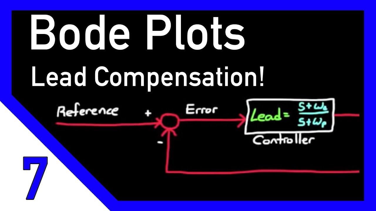
Designing a Lead Compensator with Bode Plot
Показать описание
This video walks through a phase lead compensator example using the Bode Plot method.
Errata:
Around 7:00 I added an additional '+1' in the denominator of the Ess equation. The denominator should be 0.2s^2 + s + k.
Don't forget to subscribe! I'm on Twitter @BrianBDouglas!
If you have any questions on it leave them in the comment section below or on Twitter and I'll try my best to answer them.
I will be loading a new video each week and welcome suggestions for new topics. Please leave a comment or question below and I will do my best to address it. Thanks for watching!
 0:13:58
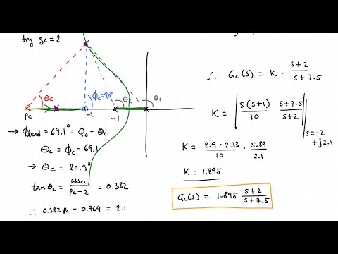
Designing a Lead Compensator with Root Locus
 0:14:19
Designing a Lead Compensator with Bode Plot
 0:28:48
Example: Design Lead-Lag Controller
 0:11:00
What are Lead Lag Compensators? An Introduction.
 0:26:15
Tutorial on Step-by-Step Design of PHASE LEAD Compensators - Control Engineering Tutorial
 0:53:03
Root Locus Lead Compensator Design Example (pole/zero cancellation)
 0:28:11
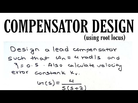
Designing a LEAD COMPENSATOR (using root locus)|| Control System|| Problem 1||Engineering
 0:07:23
Lead compensator using root locus
 0:21:25
LCS 37a - Design of a Lead Compensator
 0:04:42
Introduction to Compensator
 0:37:07
LEAD COMPENSATOR DESIGN using BODE PLOT || Control System|| Engineering
 0:23:55
Lead and lag compensation using Bode diagrams
 0:13:24
Designing a Lag Compensator with Bode Plot
 0:22:56
Problem no -4 ( Design a lead Compensator using Bode Plot)
 0:40:24
Lead & Lag Compensators Design
 0:48:37
Lead compensator design using bode plot examples | phase lead compensator solved problems
 0:22:30
Exp 11 Digital Simulation Of Lead Compensator Design
 0:16:38
Lead Compensator Design using Bode Plot/ Control System
 0:10:11
Procedure to design lead compensator using bode plot | Steps to design lead compensator
 0:29:36
Designing a LAG COMPENSATOR using root locus|| Control System|| Engineering||
 0:27:33
Designing a LEAD COMPENSATOR (using root locus)|| Control System|| Problem 2|| Engineering
 0:34:02
Design of Lead Compensator using Bode Plots
 0:17:41
3.6 Root locus design (Lead compensator)
 0:09:13
Lead compensator using bode plot
Комментарии