filmov
tv
EEVblog #1249 - TUTORIAL: Timing Diagrams Explained

Показать описание
A tutorial on how to read timing diagrams. An essential skill for designing and understanding digital logic, FPGA and microcontroller designs and datasheets.
Bitcoin Donations: 38y7DE8HEHNj8fGDtUr4PkCn9nWxiorvvy
Litecoin: ML7oQokTwB38bgzzjLDbRV97HKAHuwRfHA
Ethereum: 0x11AceA38DCA9DbFfB4F35f3F746af65F9dED28ce
Support the EEVblog through Patreon!
Buy anything through that link and Dave gets a commission at no cost to you.
Stuff I recommend:
Donate With Bitcoin & Other Crypto Currencies!
 0:36:41
EEVblog #1249 - TUTORIAL: Timing Diagrams Explained
 0:39:34
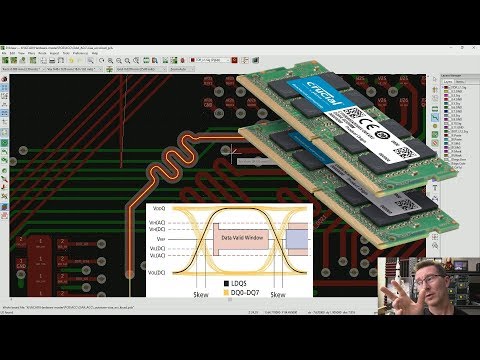
EEVblog #1247 - DDR Memory PCB Propagation Delay & Layout
 0:36:43
EEVblog #1241 - Power Up Display Counter Project - Part 1
 0:19:54
EEVblog #1235 - How To Align Signals On A Digital Oscilloscope
 0:47:45
EEVblog #1326 - How Engineering Minds Think Alike
 0:19:34
EEVblog #1252 - LED Panel Lighting Flicker Investigated
 0:58:19
EEVblog #607 - Agilent B2912A Source Measure Unit SMU Teardown
 0:28:49
EEVblog #1251 - LifeSaber Kickstarter - A Master of None FAIL
 0:52:59
EEVblog #485 - Agilent TrueVolt 34461A Multimeter Teardown
 0:14:49
EEVblog #1250 - World's Thinnest Wallet Review - Stealth Razor
 0:09:42
Blog 10 | Exploring Character LCD
 0:13:58
Pre-compliance Immunity Test - A Capacitively Coupled Pin Injection method
 0:13:27
21. Arduino for Production! AVR Atmega32 - Passing a String to the LCD
 0:29:26
EEVblog #1256 - GORGEOUS Mystery Test Gear Teardown!
 0:34:08
#04 - How To Get The Firmware - Hardware Hacking Tutorial
 0:12:56
Blips: Understanding RAM Timings
 0:04:30
Simple Diagrams 3
 0:17:12
#1237 HP3465A Multimeter repair (part 1 of 3)
 0:08:28
Commercial Smartwatch VS DIY Heart Rate Monitor
 0:14:18
Starting to look into bypassing. Sunday beginners series video (219)
 0:31:18
Hayear Microscope Camera for my OPMI-1 - (PWJ166)
 0:05:47
CSE 468 Network Security Lab 4 HD
 0:17:57
ESP8266 as Window Sensor with years of battery life
 0:07:18
(821) Picking Five Warded Padlocks
Комментарии