filmov
tv
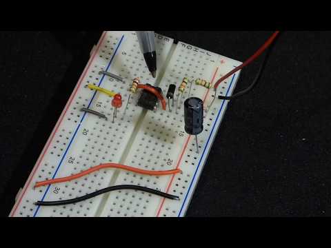
Astable adjustable 555 timer circuit

Показать описание
 0:07:17
555 timer electronics astable mode circuit step by step build demonstration by electronzap
 0:02:54
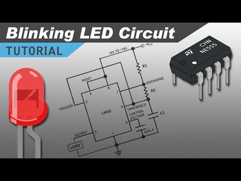
Green Blinkenlight: Creating a Simple Clock Circuit with a 555 Timer
 0:00:27
Astable adjustable 555 timer circuit
 0:06:28
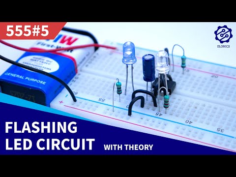
Adjustable Flashing/Blinking LED circuit on Breadboard | 555 Timer Project #5
 0:02:18
Variable resistor adjustable astable 555 timer circuit for learning electronics lesson 53
 0:03:12
The 555 Timer in Astable Mode
 0:05:55
Make ON OFF Delay Timer circuit electronics diy project
 0:02:52
555 TIMER as Oscillator (Astable mode)
 0:08:31
Adjustable Auto On Off delay timer circuit on Breadboard | 555 Timer project #4
 0:04:02
555 Timer (astable mode)
 0:18:54
555 Timers - Astable Multivibrator Configuration
 0:05:30
Time Delay Relay circuit using 555 timer IC | Off delay timer Switch | UTSOURCE
 0:06:51
Tutorial: 555 astable timer resistor and capacitor calculations | EDUQAS GCSE Electronics
 0:00:29
Astable 555 timer - 8-bit computer - Part 1
 0:34:30
Adjustable 555 Astable Timer
 0:04:46
NE555 Square Wave Signal Generator 10Khz-200khz | pcb
 0:05:22
5 second to 10 hour timer delay circuit | make a timer delay circuit controller using 555 timer ic.
 0:07:00
Adjustable Single/Dual LED Flasher Using 555 Timer IC
 0:01:02
How to Calculate 555 Timer Duration & Frequency – ATM Quick Take | Digi-Key Electronics
 0:13:24
555 timer astable mode diagram build step by step for beginner learning electronics
 0:04:08
555 timer - Astable LED Flasher / Oscillator - Two Sequence Adjustable ON / OFF Timing
 0:02:44
Traffic Light Circuit Using | 555 Timer IC | Led Projects.
 0:07:49
DIY Simple 555 Pulse Generator circuits || NE555 Frequency Adjustable Pulse Square Wave Generator
 0:07:17
TUTORIAL 8 LM555 ASTABLE MULTIVIBRATOR CLOCK WITH TIMER CONTROLLER
Комментарии