filmov
tv
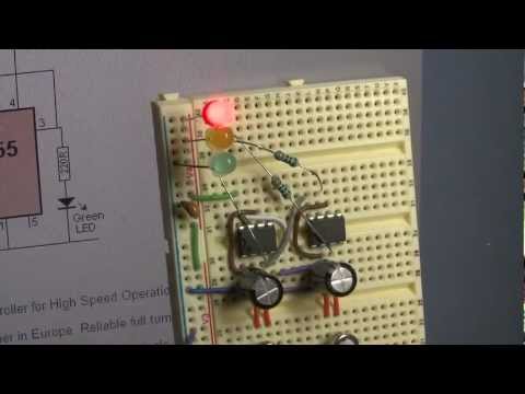
Traffic Light Circuit Using | 555 Timer IC | Led Projects.

Показать описание
Simple Traffic Light Circuit using Two 555 Timer IC.
Components Required :
555 Timer IC x 2 Nos
100uf Capacitor x 2 Nos
100k Resistor
47k Resistor
390 Ohms Resistor x 2 Nos
330 Ohms Resistor
Breadboard
Connecting Wires
Components Required :
555 Timer IC x 2 Nos
100uf Capacitor x 2 Nos
100k Resistor
47k Resistor
390 Ohms Resistor x 2 Nos
330 Ohms Resistor
Breadboard
Connecting Wires
 0:02:44
Traffic Light Circuit Using | 555 Timer IC | Led Projects.
 0:05:13
Model Traffic Lights Circuit | 555 Timer Project #15
 0:00:18
Arduino Traffic Light Demo
 0:03:44
Traffic Lights Circuit Using 555 IC | Simple electronics LED Project | with Bread board
 0:12:11
Tinercad Circuits Tutorial - Traffic Light with Arduino
 0:01:11
Traffic Lights Circuit
![[New] LED Chaser](https://i.ytimg.com/vi/KjCwehPJdHM/hqdefault.jpg) 0:02:37
0:02:37
[New] LED Chaser | Traffic Light
 0:06:21
Traffic light circuit using l 555 timer ic l project
 0:04:33
Traffic Light Circuit Using 555 Timer IC
 0:00:35
Traffic Lights Circuit on Tinker Cad
 0:02:13
Easy Traffic Light circuit with Transistor BC547🚦
 0:04:38
Simple Traffic light using BC547 transistor.
 0:00:40
Simple American-Style Traffic Signal - Logic
 0:02:49
Traffic Light Using Arduino || Traffic Light Circuit
 0:01:13
Logisim - 2-Way Traffic Light with Pedestrian Crossing
 0:13:15
Traffic light LED circuit using 2 555 Timer IC on a breadboard
 0:04:26
How to connect 3 LED with 3 Switch and 9v Battery - Traffic light project tutorial
 0:12:22
Making Traffic Lights with Arduino Uno - Beginner Level (algorithm, coding, circuit design)
 0:00:12
Four Way Traffic Light System, Traffic Light Controller Project #science #technology
 0:00:56
Flip-Flop LED Chaser Circuit | Electronics Projects | LED circuits
 0:06:52
single phase traffic light control wiring diagram with a timer
 0:05:15
How To Make Traffic Light from Cardboard
![[NEW] Simple Electronic](https://i.ytimg.com/vi/GVUuLiIg0cg/hqdefault.jpg) 0:02:28
0:02:28
[NEW] Simple Electronic Project, Traffic Light Circuit
 0:10:59
Wiring A Shop Traffic Light (The Easy Way)
Комментарии