filmov
tv
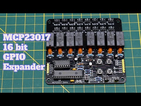
How to connect the MCP23017 GPIO Expander to an Arduino and Raspberry Pi

Показать описание
In this episode, we take a look at the MCP23017 GPIO Expander IC. With this IC, we can add 16 GPIO pins to the existing GPIO pins on an Arduino, Raspberry Pi, or any micro controller that has an i2c bus. They can be "stacked" for up to 128 additional GPIO pins! Bring on the LED's!
In this video we cover:
► Physical connection of the MCP23017 to a Raspberry Pi
► Code examples for the Raspberry PI in Python
► Physical connection of the MCP23017 to an Arduino UNO
► Code examples for the Arduino
As promised, all the code used in this video is on Github!
Parts that were used in this video:
Now go get creative! Share what you have made with me. I can be found at
If you liked this video, please consider subscribing. You can enable notifications for new videos when they are posted!
See ya next time!
#arduino #raspberrypi #makers
 0:27:15
How to connect the MCP23017 GPIO Expander to an Arduino and Raspberry Pi
 0:07:26
Zu wenig GPIO's für euer Projekt? Hir ist die Lösung, der MCP23017 | #EdisTechlab #mcp23017
 0:04:35
Interface MCP23017 (Port Expander) With Arduino Uno
 0:20:39
MCP23017 Port Expander and ESPHome: Add More I/O Pins to Your Project
 0:01:16
Arduino: How can I connect multiple MCP23017's to an arduino?
 0:01:07
How to: More IO pins for your Arduino || MCP23017 ||TechMaker
 0:07:16
Arduino Best expander Input/Output | GPIO Expansion module | MCP23017, MCP23S17
 0:05:10
#1808 MCP23017 Serial I2C 16-bit Expander
 0:01:00
Adding I/O with MCP23017 - Collin’s Lab Notes #adafruit #collinslabnotes
 0:00:48
MCP23017/MCP23S17 16-Bit I/O Expander with Serial Interface (I2C/SPI)
 0:01:23
Raspberry Pi: Don't know how to connect multiple MCP23017
 0:17:12
Arduino | Tutorial | MCP23017 Interfacing
 0:09:46
MCP23017 GPIO Expander Demo PCB: Arduino Uno Relay Driver
 0:05:19
ATTiny with 16 Extra GPIO: MCP23017 GPIO Expander with 0-Series 1-Series Devices
 0:01:00
JP’s Product Pick of the Week 2/22/22 MCP23017 16 IO Expander RECAP @adafruit @johnedgarpark
 0:04:09
MCP23017 I2C I/O Expander Module
 0:02:01
ATMega32 TWI interfaces to MCP23017 I2C I O expanding
 0:02:16
Raspberry Pi: How to use 2 x MCP23017? (3 Solutions!!)
 0:02:43
Adafruit ESP8266 Huzzah with MCP23017 I/O Expander
 0:04:56
Port Expander MCP23017 Interface with ESP8266-01 | How to Increase Number of GPIO Pins of ESP8266.
 0:00:50
STEMMA QT MCP23017 GPIO expander
 0:03:56
Read data from MCP23017 (Port Expander).
 0:01:19
Arduino: Using interrupts for two MCP23017
 0:07:15
Utilizzare il port expander MCP23017 con Arduino - Video 598
Комментарии