filmov
tv
MCP23017 Port Expander and ESPHome: Add More I/O Pins to Your Project

Показать описание
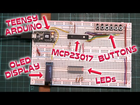
In this video, I'll take a look at using the MCP23017 16 port I/O expander with an ESP8266 (or ESP32) and ESPHome to add from 16 to 128 additional digital I/O pins to your project using just the 2-wire I2C bus from the ESP board. I'll cover the pin out, connections and limitations of the MCP23017, the ESPHome code and finally show how I use multiple port expanders to control 72 individual LEDs and three push buttons from a single ESP board to build a completely impractical clock!.
Chapter Links:
=============
00:00 Intro
01:26 ESP and MCP23017 Overview
03:57 Pinout and Limitations
06:29 ESPHome Component Mapping
07:28 Basic Bench Test
10:10 ESPHome Bench Test Config
11:29 Multiple expander wiring and ESPHome Config
13:07 A Crazy Clock Example with 75 I/O Pins
14:34 Building the Clock Face
16:16 Building the Clock Controller
18:44 Testing the Final Clock Build
19:36 Wrap Up And Other Ideas
Parts Used or Shown:
===================
You may not need all these parts, or may need additional parts, depending upon your particular project. This is just a list of what I used or showed in the video:
Other optional tools and items:
------------------------------
Some of these links may be Amazon affiliate links. Use of these links will not affect your pricing, but as an affiliate this channel may earn a small commission if you make a purchase. Any commission earned will go towards future projects and videos.
Addtional Information/Links:
===========================
If you'd like to help support this channel, or just say thanks, you can consider buying me a cup of coffee:
#esp8266 #esp32 #esphome
 0:20:39
MCP23017 Port Expander and ESPHome: Add More I/O Pins to Your Project
 0:07:16
Arduino Best expander Input/Output | GPIO Expansion module | MCP23017, MCP23S17
 0:00:50
STEMMA QT MCP23017 GPIO expander
 0:07:26
Zu wenig GPIO's für euer Projekt? Hir ist die Lösung, der MCP23017 | #EdisTechlab #mcp23017
 0:16:19
Part 2 - How to Expand Tasmota/Sonoff Devices with the I2C Protocol - MCP23017 GPIO Expansion - I²C
 0:04:09
MCP23017 I2C I/O Expander Module
 0:07:15
Utilizzare il port expander MCP23017 con Arduino - Video 598
 0:09:12
Expand your GPIO! PCF8574 & MCP23008
 0:02:28
esp8266 - need more i/o pins ?!?! ... watch this !
 0:09:04
The Great Search - I2C IO Expander (Since we can't get MCP230xx) @Adafruit @DigiKey
 0:04:56
Port Expander MCP23017 Interface with ESP8266-01 | How to Increase Number of GPIO Pins of ESP8266.
 0:16:38
Multiple Buttons with an MCP23017 on the Arduino
 0:14:16
IO Pins am ESP8266 erweitern mit dem PCF8574 Erweiterungsmodul
 0:09:46
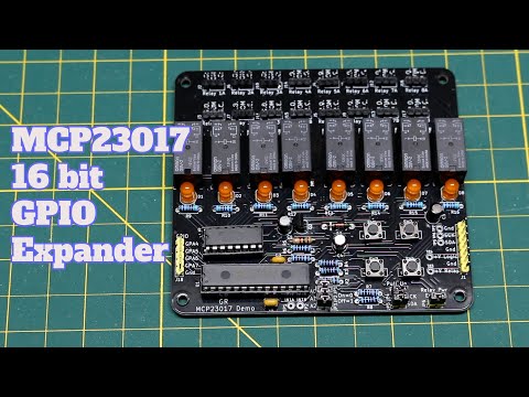
MCP23017 GPIO Expander Demo PCB: Arduino Uno Relay Driver
 0:16:58
Interface ESP32 with the PCF8575 I/O Port Expander
 0:01:00
JP’s Product Pick of the Week 2/22/22 MCP23017 16 IO Expander RECAP @adafruit @johnedgarpark
 0:00:56
Using IO expander MCP23017 with Raspberry Pi 4B
 0:24:49
Add more than 100 GPIO pins to your PICO!!!!
 0:02:16
Electronics: Wiring CJMCU-2317 MCP23017 (2 Solutions!!)
 0:01:00
Interface ESP32 with the PCF8575 I/O Port Expander #shorts
 0:05:10
GPIO Expander COMPLETE User Guide (for beginners)
 0:14:41
Part 1 - How to Expand Tasmota/Sonoff Devices with the I2C Protocol - I²C
 0:11:12
Lesson19- how to use PCF8574 IIC extend GPIO for ESP32 multi relay
 0:00:24
MCP23017 PCB blinking LEDs
Комментарии