filmov
tv
Ultrasonic Sensor HC-SR04 and Arduino Tutorial

Показать описание
Please note, circuit diagram at 0:56 should be: 5v to VCC, GND to GND, D10 to Trig, D9 to Echo.
In this Arduino Tutorial you will learn how to use the HC-SR04 Ultrasonic sensor. It can measure distance from 2 cm to 4 meters with a ranging accuracy up to 3mm. The working principle of this module is quite simple.
Like my page on Facebook:
Add me on Google+:
In this Arduino Tutorial you will learn how to use the HC-SR04 Ultrasonic sensor. It can measure distance from 2 cm to 4 meters with a ranging accuracy up to 3mm. The working principle of this module is quite simple.
Like my page on Facebook:
Add me on Google+:
 0:05:28
HC-SR04 Ultrasonic Distance Sensor and Arduino (Lesson #9)
 0:05:16
Ultrasonic Sensor HC-SR04 and Arduino Tutorial
 0:06:01
Ultrasonic sensor HC-SR04 with Arduino(code explained) Distance Measuring Senosr -Arduino tutorial 9
 0:06:04
Ultrasonic Sensor HC-SR04 and Arduino Tutorial
 0:05:12
Ultrasonic Sensor HC-SR04 Arduino Tutorial
 0:07:22
Arduino ultrasonic sensor led projects | Hc-sr04 Ultrasonic sensor
 0:00:17
Ultrasonic sensor Hc sr-04 #circuit #arduino #automobile #tecnology #diy #robotic #sensor
 0:48:03
Using the HC-SR04 Ultrasonic Distance Sensor with Arduino - Everything you need to know!
 0:00:19
HC-SR04 ultrasonic sensor with OLED display
 0:04:07
Using Ultrasonic Distance Sensor HC-SR04 with Buzzer, LED and Arduino
 0:05:04
How to use Ultrasonic Sensor HC-SR04 with Arduino
 0:12:03
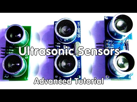
#40 Ultrasonic Distance Sensors Arduino Tutorial and Comparison for HC-SR04, HY-SRF05, US-015
 0:00:13
HC-SR04 Ultrasonic Sensor / Arduino Nano - Test
 0:05:30
Using Ultrasonic Distance Sensor HC-SR04 with LCD Display and Arduino
 0:07:59
Tutorial on Ultrasonic sensor HC-SR04 - Connections, interfacing & coding with Arduino
 0:01:17
Ultrasonic Sensor HC-SR04 and Arduino Tutorial#arduino
 0:07:10
Distance Meter / Range Finder using Arduino Uno & HC -SR04 ultrasonic sensor || Arduino Project
 0:03:48
Ultrasonic Distance Sensor HC-SR04 | Arduino Basics Tutorial
 0:04:31
ESP32 Review: Arduino and Ultrasonic sensor (HC-SR04)
 0:03:43
HC-SR04 Ultrasonic Sensor Tutorial with Arduino
 0:00:57
Arduino autonomous car with ultrasonic sensor (HC-SR04)
 0:00:30
Ultrasonic Sensor HC-SR04 and Arduino
 0:02:49
Arduino UltraSonic Sensor Tutorial
 0:04:11
Arduino HC-SR04 Ultrasonic Sensor with TM-1637 Display || VIKRAM TECH
Комментарии