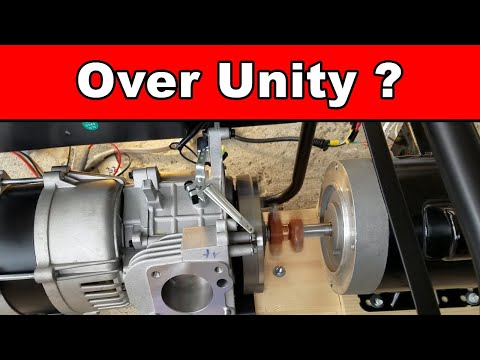
Over Unity - FREE Energy - Using A Gas Generator Components (Is It Possible?)

preview_player
Показать описание
Is it possible to generate free energy using a gas generator components?

Рекомендации по теме
Комментарии
Автор

One of the missing parts to your system is a big enough flywheel to keep generator turning until motor can take over.

lablancengineering
Автор

Thank you for wasting your time and money instead of me wasting mine.😊

edwinlipton
Автор

I tried with a small motor using a drill to see if the lamb would actually lights up ... but no luck . . Your testing saved me a lot of work .. thank you

jamesdemuro
Автор

YOU HAVE TO ADD NEODYME MAGNETS ON THE ROTOR OF THE GENERATOR !!!

In a conventional generator there are current driven coils, which produce a magnetic field
in the rotor, which passes the outer coils of the stator during the rotation.
The stronger these neodyme magnets are,
the stronger is the induced current in
the outer stator coils during the rotation
of the rotor.

sciencesymphony
Автор

The motor is synchronous motor, meaning that it follows the electrical phase of its current source.
It cannot run out of phase with the electricity.
So when powered by the generator the two must have electrical phase timed correctly.
If the mechanical connection is not set with correct phase timing then the motor cannot latch to the current phase and will not run.
Like trying to run a fuel engine with incorrect valve timing.
You must set the electrical timing before locking the motor to generator with the mechanical connection.
Power is irrelevant, because rotating the system with no external load requires low power from motor.
Generator and motor are both rated to make adequate power to spin each other, but...
Electrical efficiency is what matters for closed system operation. If motor efficiency minus parasitic losses is greater than generator efficiency then it will run if timing good.
How to set timing: mark the pulleys so the angles can be registered relative to each other and experiment with advancing timing in 5 degree increments = 72 possibilities. If it runs, then fine tune timing for max rotation speed. If it doesn't run, nice try! and thanks for the entertainment.

rhollyday
Автор

You have no heavy flywheel. Use 10-15kg flywheel to store energy for use during transition from wall power to generator

simon
Автор

Overunity is real, the whole world is run on that principle, don't let no one tell you it is false, you just have to know what you are doing

leroysmith
Автор

Excellent experiment. I think this is possible considering all the variables involved. It takes a lot of failed experiments to come up with the over unity. The answer lies just around the corner.

mastertradersph
Автор

Reply: Wow, that Segway Portable PowerStation Cube Series sounds like an amazing piece of gear! I love how it offers a massive capacity and fast recharging, perfect for powering our outdoor adventures or serving as a backup power source at home. The waterproof technology is also a great feature. Thanks for sharing this recommendation, I'll definitely check it out!

CherokezPittman
Автор

The AC synchronous motor runs on wall power because it is allowed to follow AC current phase, but when it's mechanically locked to the generator's input shaft the motor is not allowed to synchronize itself to the generator output current phase so it cannot run. The phase of the motor's input current must be timed for max power with the output phase of the generator. Motor slightly lags the input current, proportional to the torque output, so they are never perfectly phase-aligned. This relative phase angle is adjusted at the mechanical coupling where the shafts lock together. Adjust in 5 degree increments until it runs, then optimize in 1 degree increments. OR use a 2 channel oscilloscope to adjust the mechanical shaft coupling so the phase angle of generator output matches the phase angle of utility power (motor input phase) while the wall-powered motor is driving the generator while the expected load (angle grinder) is running off generator power. With mechanical phase aligned like this, when you switch motor over to generator power the phases will be timed correctly and motor will drive the generator. Removing the gas engine friction will allow higher generator loads. System output is limited by the smaller of the motor or generator wattage ratings.

rhollyday
Автор

I'm very sorry you had to loose your precious time on this. I found a way to understand all of this by thought in my childhood. Than I've lost time on more complicated concepts. Now I'm probably ready to rock.

grazianoturbogas
Автор

It's a bit like pouring a gallon of water into a bucket and expect to get two gallons of water out.

ericchapman
Автор

Hello. Very short experiment. Need a proper flywheel/inertial wheel for the system and a proper set of ratio wheels to sweet spot the rotations in each motor/motor generator. The flywheel should be a disc-like one but it is not all about just its weight. The mass should be moved more towards the max radius and lighter to the center of the disc, as long as there is no issues on the structural resistance of the disc under maximum rotation (of the system). Also have to have a feed in the coils of the generator or use a permanent magnet configuration on it.

MagneticBlueSky
Автор

Hello, Mr Tiger. I used this same generator, champion 1500 / 1200. The engine was kaput. So i took off those small 8 mm bolts, holding the motor, to the base end plate. The oil fill hole, is on this plate. 2 bolts don't come out of the plate, between genhead and it. Removed long through-bolt, holding the tapered end motor shaft, to the gen rotor. It broke loose, after putting a small bolt in the gen head end. (Hammer it out ) Took off the engine, from the rest of it. Okay. Now, angle grinder / grind off the crankshaft, right at the gear. You'll need all of the shaft, of the tapered part (about 3 inches...).
To extend the rotor drive shaft ( the 3 inch one, cutoff from engine crank by that cam gear - it is plastic) i cutoff the head of a grade 8 bolt - same diameter as shaft . Centred it with 2 90 degree triange magnets. (after grinding a taper on the bolt shaft - for facilitating the weld) MIG welded it. Then, checked for total centerdness. Good . DC welded it, with 105 amp setting -6013 rod.
Ground down it smooth on home made 2 x 42 belt sander. Good to go. Re-installed everything again. (throw engine part away) Now, i've got a genhead, makes power. All that is left, is to make a cover plate, so as to keep the drive end bearing, lubricated. A home made steel plate, 16 gauge or so should work. I'll have to add a seal, between this plate and the shaft. Shouldn't be too difficult. Anyway...take care all ! Stay learning and Creative ! ( my plan, is to install this in my older intrepid car - where the AC compressor was. Will have to figure out, pulley diameters - for 3600 rpm at idle. Anyway....take care !

petersack
Автор

1) Only if you add neodymium rotor and remove the rotor coils. Add battery bank and inverter to power the motor. The generator excess power will charge back to the battery bank. Or use the grid tie method, loop back the output power to the outlet in your house.

thienvu
Автор

If you were to monitor 1) supply voltage 2) internal resistance 3)counter electromotive forces 4) voltage drop as the load changes
In real time you will see that the sys is too simple and does not address all issues.

denniswhitley
Автор

The error comes in during the change over. You need a power bank either in the form of inverter or flywheel that would store power for use during change over. When maximum speed of flywheel is attained, then put on the switch linking a contactor switch to the dynamo supply (output) which will eventually close and then forward it's power to the driver motor. The energy stored in the spinning flywheel will keep the system running during change over. This should work using a low rpm dynamo.

ithinkican
Автор

I am a Nigerian. If u can follow this steps u are good to go . 1. Let the first motor spin it to give out the total output of the gen before you connect the 2nd motor. 2. Make a power factor correction to the system by adding stating capacitor to the 2nd motor so that I will reduce the amperage required

tijanifuhad
Автор

Thank you idol.. 👏👏👏👍
I Hope that your experiment is Successful . I'm waiting for the next results. Support From The Philippines 👍👏👏❤️

PapsTolitsVlog
Автор

Use the DC inverter motor to move the generating head, you must take into account the number of revolutions per second in order to adjust with you

daaraade