filmov
tv
Magnetic Flow Meter Explained | Working Principles

Показать описание
▶ You can read the full post here
⌚Timestamps:
00:00 - Intro
00:51 - What is a Magnetic Flow Sensor?
01:46 - The Magic is in the Magnet
03:09 - Faraday’s Law
05:19 - Conductive Fluids
06:41 - Other Considerations for Installation
09:12 - Summary
=============================
Magnetic flow sensors are a very commonly used flow meter type that is useful in a wide range of applications and line sizes.
Accurate and repeatable measurement of flow is a requirement for industrial processes, including feed streams, tank recirculation loops, product transfer lines, and many others.
In this video, we will
- Introduce you to the working principles of a magnetic flow sensor,
- Describe the physical characteristics of a magnetic flow sensor that make it valuable for process control,
- Describe the ways magnetic flow sensors can be integrated into a measurement and control system.
Magnetic flow sensors convert the velocity of a flowing fluid into a measurable electrical signal that is proportional to the flow rate.
Magnetic flowmeters have no moving parts or internal flow path obstructions, so they are easy to calibrate and maintain.
Because magnetic flow meters are typically specified to be the same size as the upstream and downstream piping, there is virtually no pressure loss through the flow meter, which can be very advantageous for some flow streams, like thick slurries.
Magnetic Flow sensors are often called mag meters, and we will refer to them using this abbreviation.
Mag meters are typically full-bore sensors, meaning that the internal flow path is of the same diameter as the upstream and downstream connections.
This construction eliminates any restriction of the fluid which may alter the flow path or create a pressure drop.
Fluid passes through the mag meter in a straight line through the bore of the sensor. This regular, cylindrical geometry also allows a constant and directional magnetic field to be established across the diameter of the flow path.
The magic that creates the flow signal is based in the magnet! The mag meter is surrounded by an iron-core, permanent magnet that creates a magnetic field to be established with lines of magnetic flux which pass vertically through the entire cross-section of the pipe and the flowing fluid.
This geometry is very important. The flowing fluid will pass through these lines of magnetic flux at a 90-degree angle or perpendicular to the lines of magnetic flux.
To generate a voltage according to Faraday’s law, we must have a moving conductor.
The conductivity of liquids is measured in units of micro-Siemens-per-centimeter. Some fluids, such as seawater, have high conductivity, and seawater flow can be measured with a mag meter.
In addition to seawater, flows of wastewater, and ionic solutions such as acids can easily be measured by magnetic flowmeters.
When installing a magnetic flow meter in process piping, it is vitally important to follow the manufacturer’s recommendation for grounding.
The electrical signal produced in a mag meter is a very small DC voltage, and stray voltages along a pipe due to welding equipment or other large electrical loads in the plant.
Transmitters are always used with mag meters. They convert the small DC voltages generated by the flowing fluid into signals that can be connected to the control system.
4 to 20 milliamp, Profibus PA, Foundation Fieldbus, and IO-Link transmitter outputs are available.
When specifying magnetic flowmeters, some important aspects must be considered in addition to the conductivity of the fluid and the need for grounding rings.
If the fluid is corrosive or abrasive, a compatible liner should be specified. These liners can also be replaced if they become worn, and they do not affect measurement accuracy.
=============================
=============================
Missed our most recent videos? Watch them here:
=============================
To stay up to date with our last videos, make sure to subscribe to this YouTube channel:
=============================
=============================
#RealPars #sensor #flowmeter
 0:10:29
Magnetic Flow Meter Explained | Working Principles
 0:03:57
How a Magnetic flow meter works. working principle of magnetic flow meter. English Animation
 0:04:45
Magnetic Flow Meter Explained
 0:01:38
What is a Magnetic Flow Meter and How Does it Work (measuring flow)
 0:08:05
Turbine Flow Meter Explained | Operation and Calibration
 0:06:20
How does Electromagnetic Flowmeter work | Flow measurement Techniques
 0:10:14
How to Measure Flow with Magnets - (Magnetic Flow Meters)
 0:06:09
How Flow Meters Work
 0:11:37
Types of Flow Meters in Piping (8 Types)
 0:00:46
Magnetic Flow meter principle 3d
 0:07:04
Quick Setup and Configuration with Azbil Magnetic Flow Meters
 0:05:50
Mag Flow Meter Basics
 0:03:45
Magnetic Flow Meters - Family Overview from AutomationDirect
 0:05:12
Magnetic Flow Meters - Large Meters Quick Start from AutomationDirect
 0:08:23
Ultrasonic Flow Meter Explained | Working Principles
 0:02:37
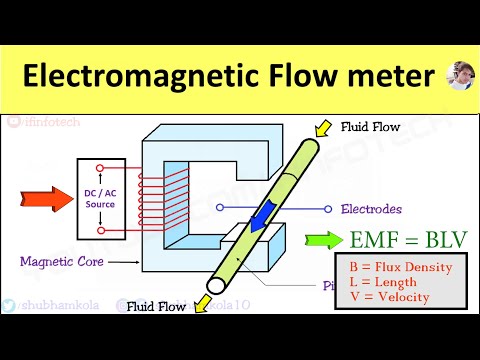
ELECTRO MAGNETIC FLOW METER WORKING PRINCIPLE
 0:05:54
10. Magnetic Flowmeter (ADMAG Series) - User Oriented Functionality -
 0:15:07
Electromagnetic Flowmeter | Working and Principle of Electromagnetic Flowmeter | Mag Flowmeter |
 0:05:44
How electromagnetic flow meter works
 0:01:35
What is a flow meter and how does it work? Explained
 0:08:26
Magnetic Flow Meter| Electromagnetic Flowmeter | How Magnetic Flow meter works | Learn with Labtech
 0:03:45
How to Calibrate Magnetic Flow Meter
 0:06:29
Magnetic flow meter
 0:02:10
Electromagnetic Flow Meter: Working Principle, Advantages & Disadvantages, Flow Rate Measurement
Комментарии