filmov
tv
Arduino Tutorial for Beginners 11 - Analog Signal Output (PWM) (Control Speed of DC Motor)
Показать описание
Welcome to this video on Arduino Tutorial for Beginners. This video about Analog Signal Output (PWM)
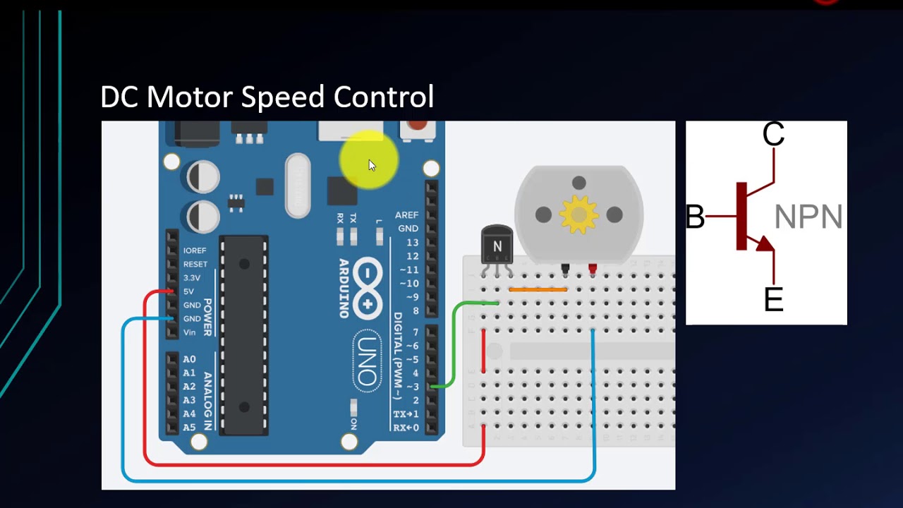
This video shows how to control speed of DC Motor with a little bit transistor knowledge. Arduino lacks a true analog output, so we need to use Pulse-width modulation (PWM) to simulate a variable DC supply voltage. PWM is a common procedure for supplying variable power levels to “slow” electrical devices such as resistive loads, LEDs, and DC motors. Pulse-width modulation (PWM) provides the ability to simulate varying levels of outputs.
Arduino Uno has 6 PWM pins: Digital I/O pins 3, 5, 6, 9,10, and 11
Make Fading led and Control RGB led
Code :
analogWrite(_pin,value)
_pin is the PWM pins (has tilde before) and value from 0 to 255
Arduino programs, called “sketches”, are written in a programming language similar to C and C++. Many sensors and other hardware devices come with prewritten software – look on-line for sample code, libraries (of functions), and tutorials. Learn the Arduino platform and programming language to create robots, interactive art displays, electronic gadgets and much more.
#ProgrammingKnowledge #Arduino #ArduinoTutorial
★★★Top Online Courses From ProgrammingKnowledge ★★★
★★★ Online Courses to learn ★★★
★★★ Follow ★★★
DISCLAIMER: This video and description contains affiliate links, which means that if you click on one of the product links, I’ll receive a small commission. This help support the channel and allows us to continue to make videos like this. Thank you for the support!
 0:25:07
Arduino Tutorial 11: Understanding the Arduino Serial Port and Print Commands
 0:13:56
Arduino Tutorial for Beginners 11 - Analog Signal Output (PWM) (Control Speed of DC Motor)
 0:10:35
Lesson 11 | Understanding loop() and setup() | Arduino Crash Course
 0:00:21
learn Arduino programming in 20 seconds!! (Arduino projects)
 0:14:13
Tutorial 11: If Statement Conditionals: Arduino Course for Absolute Beginners (ReM)
 0:03:53
Arduino Tutorial: LED Sequential Control- Beginner Project
 0:10:00
How PWM Pins Work (With Code) - Arduino Tutorial for Beginners 11
 0:09:52
What is Arduino and can I use it for my project? [Beginner Friendly]
 0:15:38
bts7960 motor driver FULL CODE | arduino 775 motor driver | All about 775 motors | complete lesson
 0:04:27
Arduino Tutorial - 11. Der Lichtsensor (#11)
 0:00:14
LCD Display with Arduino #arduino #diy #programming
 0:00:07
Arduino Code -- DC MOTOR #arduinoprogramming #arduinosoftware #arduinocode #code #arduino
 4:04:22
Arduino Course for Beginners - Open-Source Electronics Platform
 0:08:14
Workbench Essentials When Starting Arduino! (Beginner Guide)
 0:00:08
Open lock with a RFID Reader using Arduino 🔐💳😲 #diy #arduino #arduinoproject #howto #how #electronic...
 10:28:56
Arduino Course for Everybody
 0:00:15
Uno R4 Wi-Fi - How to connect Uno R4 Wi-Fi to the Arduino Cloud #electronics #engineering #tech
 0:00:11
LED Matrix - Arduino Project for Beginners #arduino #engineering #diy
 0:00:30
Amazing Experiment with Arduino Nano | Flappy Bird Game #diyprojects #arduino #3dprinting #tech
 0:00:15
Top Five Arduino Projects #diy #arduino #arduinoprojects #experiment #eazytronic
 0:17:40
ARDUINO BASICS #11 - Taster an digitalem Eingang
 0:00:11
DIY Radar System using Ultrasonic Sensor and Arduino #roboarmy #stemeducation #scienceproject
 0:00:18
Simple Arduino & Python Projects 👀🧑🏻💻💫 | #arduino #python #opencv #electronic #computervision...
 0:00:18
Arduino Motor Shield#arduino #motorshield #electronicproject #engineering #electrician
Комментарии