TSP #131 - Teardown, Repair and Analysis of an Agilent 8449B 1.0 - 26.5GHz Microwave Preamplifier

preview_player
Показать описание
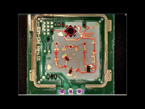
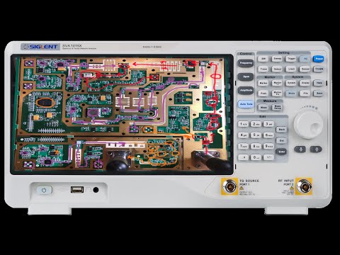
In this episode Shahriar analyzes the failure of two Agilent 8449B Preamplifiers. These units should provide up to 30dBm of gain from 1.0GHz to 26.5GHz intended for use as a preamplifier. Both amplifiers test positive for power supply voltages and operation. After removing the interface cables from the amplifier module to the front panel, it becomes clear that mechanical shock has caused damage to the front panel connectors. Replacement cables and connectors are used to correct the problem.

The Signal Path
Рекомендации по теме
Комментарии
Автор

Based on the feedback from all of you, it seems everyone wants the unit to remain intact. I will therefore not break it. I am sure there will be lots of microwave components to take apart in the future.

Thesignalpath
Автор

I’m happy that you chose not to risk damaging the working unit. These pieces of test gear are a fairly precious resource to people who don’t have corporate budgets to fund their obsessions :)

AndySpicer
Автор

Great video, per the usual.
Dont break that rf amplifier!
_we're not worthy, we're not worthy_

Thank you again for selflessly sharing your wisdom.
You are a god amongst men

topherteardowns
Автор

For goodness sake don't break it!!! Another great video, thanks!

PapasDino
Автор

Please don't destroy it!!! I'd feel guilty if you did! Very cool none the less.
Hope you can do a video on leveling. As an approximation I guess that could be achieved by the output of the detector (the 3.6Ghz amp you dismantled) being used to adjust the bias of the final stage amplifiers?

vincei
Автор

Great troubleshooting. Yes no need to break that apart. We get it. Thanks for sharing.

TheRadioShop
Автор

“1 volt off shouldn’t break it” - I hit my head against the wall a few times when I used a cheap meter(the good one was in storage at the time) to try and fix an HP 5316A, when I finally noticed that the voltage spec in the service manual was 5v +/- 0.01v. Talk about a tight spec! A slight tweak with a more precise meter and it instantly started working.

CatCow
Автор

I like your videos because you take advantage of the things that others have taken for damaged. (It is like what is said that the trash of some is the treasure of others) and I do the same here in Venezuela repairing and recycling electronics and multimeters for my own mini instrumentation laboratory

apresuntuoso
Автор

Excelente...!!! Saludos desde Mexico...!!!

joaquinlop
Автор

DON'T BREAK IT! Maybe you can sell the other amplifier and use the proceeds for more instruments to repair? It's so often that the reason an instrument is discarded is some simple failure that is relatively easy to fix. Your troubleshooting and analysis is excellent. I would like to learn more about coaxial cables for microwave use. I'm not familiar with the characteristics of cables beyond 500 MHZ.

billmoran
Автор

An excellent video demonstrating the often overlooked importance of input and output connections. I assume that the solder used in the manufacture of those rigid cables is most likely a lead-free type, which in my opinion most likely was the weak point in the connection. In my experience with lead-free solder alloys most tend to be fragile when subjected to repeated tiny mechanical stresses. I have seen rigid connections in field test equipment that were manufactured long before the introduction of lead-free solder that showed no such signs of cracking even on connectors with much less strain support at the mounting points. Communications test gear that had 20+ years of daily field usage, transported in less than ideal conditions, used in outdoor environments with no such problems with solder joints on rigid connectors. An example of why a connection that was most likely designed to be assembled with a lead-based solder should not have been assembled with a lead-free solder alloy. Just my assumption and opinion based on observations of the usage of both types of solder in many different types of connections that are subjected to any type of mechanical stress from flexing to even very slight vibration.

marklange
Автор

I have one of those power supplies and another one which is +/-12V. They both came out of an external drive enclosure from the early 1980s. Clones of these power supplies are being made nowadays by a handful of US manufacturers.

douro
Автор

Discovered your channel couple of days ago, can't stop watching your videos, extremely helpful. Very detailed and nice mix of theory and practical experiments, fun! Clearly you are very intelligent, gifted and natural at teaching. Thank you for taking your time to create & share these wonderful videos with us! Keep up the great work! I think you, Dave/EEVblog, Afrotechmod and Electroboom should team up and create your own online type of nano EE degree or program or may be partner with Udacity or such :)

mazenl
Автор

Nice video as usual Shahriar, ...
It never ceases to amaze me the advances in electronics some companies like HP have made since the 40's.
Early forties tech may have included scopes but they didn't have trigger inputs or a scaled output to measure accurately.
Tektronix introduced gigantic leaps forwards in scope design and they still do. HP or Agilent or Keysight, which ever flavour you prefer have in the most part introduced other measuring equipment that have broken frequency boundaries. The maths involved to create substraights like the Amplifier you show here are incredible and I imagine needed years of RnD to perfect. They look deceptively simple but look at your substraight with the Diode on the right, the extended track, I think you said was to null out the diode parasitics... yes an inductor at those frequenciea and maybe capacitance through the substraight to make a filter but clever and needed to be calculated precisely.
These companies may demand high prices but if you can afford their equipment, you can't go wrong.... GEC in the eighties where I worked were full of HP equipment (Mostly) or 4.5 digit Fluke meters, so much money spent in getting the best.

michaelhawthorne
Автор

While I would love to see one, I'd prefer you keep it intact - it would be just too much of a waste. Thanks for another great video.

davidgustafik
Автор

Neh. Leave it working. Useful piece of kit. A bit big, but useful.

Maybe modify one units, and put TWO modules into it? To conserve some bench space. :) Might require upgrading PSU PCB, but maybe the existing can do it.

Greate video.

movaxh
Автор

Hi Shahriar,

Thanks again for yet another great video that teaches total RF dummies like, a lot every time...

You might want to correct the title of this video ? You forgot to add the numbered prefix to it, like " TSP # 131 - " ;-)

Looks like your channel is doing really well : if memory serves me correctly (?) when I subscribed to your channel, no more than 12 months ago IIRC, you had 17K subscribers, and now 54K ?! :-O That's going exponential eh ?
Well deserved of course ! Hoping it will keep sky rocketing :-) Keep up the excellent work, always much appreciated ! :-)

Vincent Trouilliez

troutrou
Автор

This is not the EEV blog: Turn it on, don't take it apart.

frankderks
Автор

On the last unit you showed, the output coupler looks to me like it would measure reflected power, not forward power, based on the location of the load resistor and the output to the detector.

sbreheny
Автор

Very good investigation - but a small critisism - knowing that the front panel was pushed in I would have immediately inspected the connectors and cable path from the panel. The damage you observed to these would mean that it was not strictly necessary to carry out that extensive trouble shooting.

fardellp