filmov
tv
TSP #35 - Teardown, Analysis and Repair of an HP/Agilent 5347A 20GHz Frequency Counter & Power Meter

Показать описание
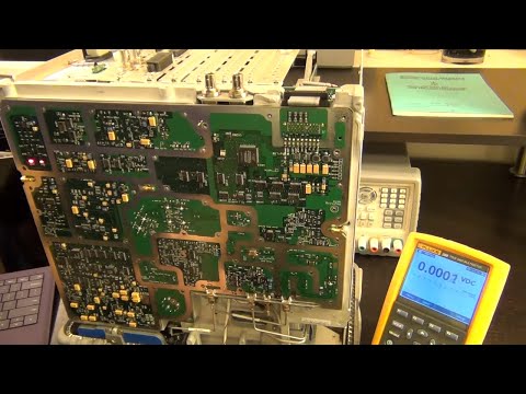
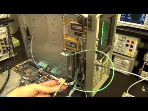
In this episode Shahriar takes a close look at an HP/Agilent 5347A 20GHz Frequency Counter and Power Meter. This defective unit does not provide any frequency information from Input 2 which is rated to operate up to 20GHz. Before the teardown and repair attempts, the principle operation of the instrument is reviewed.
The properties of a Step Recovery Diode (SRD) is presented along with the theory and practical aspects of generating a frequency comb. The heterodyne architecture of the frequency counter is explained in detail with the mechanism of detection and calculation of the input frequency.
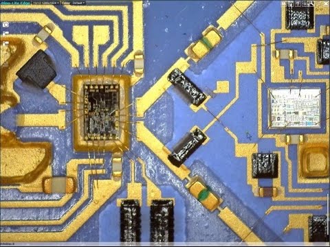
During the teardown of the unit the synthesizer board, motherboard, power meter reference board and the main RF assembly are shown. The schematic of the synthesizer board and the RF board are also described. The defective component is identified and examined under the microscope. The slides for this episode can be found at The Signal Path website.
The Signal Path
The properties of a Step Recovery Diode (SRD) is presented along with the theory and practical aspects of generating a frequency comb. The heterodyne architecture of the frequency counter is explained in detail with the mechanism of detection and calculation of the input frequency.
During the teardown of the unit the synthesizer board, motherboard, power meter reference board and the main RF assembly are shown. The schematic of the synthesizer board and the RF board are also described. The defective component is identified and examined under the microscope. The slides for this episode can be found at The Signal Path website.
The Signal Path
 1:02:38
TSP #35 - Teardown, Analysis and Repair of an HP/Agilent 5347A 20GHz Frequency Counter & Power M...
 2:02:04
TSP #34 - Teardown, Analysis & Repair of an Agilent E4407B 26.5GHz ESA-E Spectrum Analyzer
 0:48:41
TSP #122 - Teardown, Repair & Upgrade of an Agilent 3458A 8.5 Digit Digital Multimeter (April 20...
 0:36:30
TSP #250 - Tektronix TriMode Active 10GHz (TDP7000) Probe/Tips Review, Teardown & Experiments
 0:45:13
TSP #46 - Teardown, Analysis and Part-Salvage from an HP 70001A Series Optical Microwave Analyzer
 0:51:23
TSP #134 - Teardown, Repair & Analysis of an Agilent N5230A 13.5GHz PNA-L Network Analyzer (Part...
 0:37:38
TSP #206 - Keithley 2281S Precision Power Supply & Battery Simulator Review, Teardown & Expe...
 0:20:36
TSP #225 - Agilent E5052A 7GHz Signal Source Analyzer Teardown, Repair & Experiments
 0:54:35
TSP #113 - Teardown, Repair & Analysis of an Agilent E4443A 3Hz - 6.7GHz PSA Spectrum Analyzer
 0:30:57
TSP #83 - Teardown & Analysis of an Agilent 86109B Optical/Electrical DCA-X Oscilloscope Module
 0:48:46
TSP #155 - Keithley DAQ6510 6.5-Digit Data Acquisition & Multimeter Review, Teardown & Exper...
 0:41:55
TSP #103 - Teardown & Repair of an Agilent 53152A 46GHz Microwave Frequency Counter
 0:21:27
TSP #124 - Teardown & Repair of an Agilent E4440A 3Hz - 26.5GHz PSA Spectrum Analyzer
 0:53:40
TSP #75 - Tektronix TSG4106A RF Signal / Vector Generator Review, Teardown & Experiments
 0:22:35
TSP #106 - Teardown & Repair of a Fluke PM6685R 4.5GHz Rubidium Frequency Counter
 0:22:46
TSP #63 - Teardown & Analysis of a Keysight InfiniMax III N2802A 25GHz Active Probe
 0:36:52
TSP #55 - Teardown & Repair of an Agilent E3631A 6V/25V 80W Triple Output Power Supply
 0:52:13
TSP #47 - Teardown, Repair and Analysis of an HP 8562B 22GHz Spectrum Analyzer
 0:46:45
TSP #72 - Teardown, Repair & Calibration of a Fluke PM6680B 225MHz High Resolution Frequency Cou...
 0:38:18
TSP #199 - Digilent Analog Discovery Pro 3000 Series (ADP3450) Review, Teardown & Experiments
 0:40:00
TSP #234 - QuantAsylum QA403 24-bit, 0.0001% THD Audio Analyzer Review, Teardown & Experiments
 1:07:51
TSP #121 - Rohde & Schwarz FPC1500 5kHz - 3GHz Spectrum Analyzer Review, Teardown & Experime...
 0:22:52
TSP #175 (I) - Teardown & Repair of a Fluke 744 Documenting Process Calibrator (Part 1)
 0:20:15
TSP #90 - Teardown & Analysis of an Anritsu MN9610B Variable Optical Attenuator
Комментарии