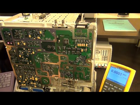
TSP #129 - Teardown, Repair and Analysis of an Agilent 4338B (10uΩ - 100kΩ) Milliohmmeter

preview_player
Показать описание
In this episode Shahriar repairs an Agilent 4338B milliohmmeter. This instrument is capable of measuring extremely small resistances down to 10uΩ while maintaining a DUT voltage of less than 20mV. The instrument powers on with the message ADC Failure. Investigation reveals that the instrument uses an obsolete ADC which must be removed from the board in order to reverse engineer its operation. While the ADC turns out to be functional, a PAL device which controls the ADC timing is faulty. A new device is salvaged from a donor board to complete the repair. The instrument is then used to measure several small known resistances.

The Signal Path
Рекомендации по теме
Комментарии
Автор

A few words on HP part numbers... Firstly, HP used their own part numbers for generic parts and often had manufacturers mark them with the HP number. Generic part numbers consist of two groups of four digits. The first four digits tell you what type of part it is. For example with part 1854-1028, the 1854 tells you it is a silicon NPN transistor, and the 1028 tells you it's a 2N3904. Many HP service manuals up to the 1980s contain replaceable parts lists that actually cross reference HP numbers to the manufacturer's original designation, so if you have a part with one of these HP numbers on, but don't have the service manual, it can be helpful to search through other HP service manuals for instruments likely to contain the same part.

Other parts, like the PAL in this video, have 10 digit numbers. These are parts specific to one instrument or a few instruments. They can be used for individual parts or for sub-assemblies. The format of the number is 'abcde' is the model number of the instrument, with a leading zero for four digit model numbers. If the first digit of the second group began with a 6, this generally meant it was a complete board as I recall. There used to be a program where defective boards replaced in field service were sent back to the factory for repair. These came back with the second digit of the second group replaced by a 9. The PAL in question here was used originally in the 4263 LCR meter. I hope somebody finds this info useful. Apologies if I made any errors -- it's a long time since I was a field service engineer.

oldblokeh
Автор

Thanks for the memories. I was the HP product manager on the 4263A, 4338A and 4339A. Fun stuff working with my Japanese colleagues.

alanfryer
Автор

I have a 4338A on my workbench for happy to see Shahriar working on the 4338B and providing info on the AK9201A ADC. Gives me a great place to start.

IanScottJohnston
Автор

For a minute there it was fun to see a few basic components in a breadboard like us regular mortals. Then all goes back to normal as he plugs it in to a thirty thousand dollar 'scope. Sigh. :-)

JamesLebihan
Автор

No doubt you know the “word” ADC but I’m not sure whether you know the word failure.
Just wanna express my appreciation for the superb videos you make. Thank you big time.

pv
Автор

The PALCE 16V8 family does indeed allow for outputs to be registered. However, it does not have "internal-only" registers, e.g. you cannot have hidden state in the chip. It has only one type of macro cell. If you want a flipflop which acts as an input to another logic cell, you can use internal routing of a !Q output to the neighboring cell, but at the same time, the non-inverted Q output of the flipflop is available on a pin. So it is quite possible to reverse engineer those, even if this is mask-programmed (and another commenter stated that it might not be).
16 inputs, 8 outputs, slowest speed grade. Probably not even all inputs used. That's a truth table that can be (reverse) engineered by hand. Contact me if you want to discuss options on doing that.

crazor
Автор

Apparently those PAL device can be read in some way or form, as LSC suggest in their PAL to GAL datasheet "A GAL device may also be programmed from a master PAL device by reading the pattern of the master PAL into
the programmer memory"

I could imagine, that the EE memory on the PAL is just corrupted due to aging (it has a nominal data retention of 10/20 year depending on temperature). So it could be as easy as reading the "good" PAL into a programmer and re-writing the "dead" PAL.

PS: The datasheet actually mentions something about a security bit so it may be a bit more tricky. But reverse engineering the truth table of that pal should make a fun video ;-)

berniwa
Автор

Thank you for sharing your knowledge! (And thanks Patrons for supporting him <3) Just started the video, but wanted to say thanks!

ThinkinThoed
Автор

Great video Shahriar :-) The ferrites on the coax cables you are talking about at 3:05 are not for getting rid of any transients. They are acting as a common mode chokes to reduce common mode signals that could enter front end amplifier and affect its operation.

adamturowski
Автор

I hope you find the part you need. Thanks for helping me understand some very advanced topics for this hobbiest. Makes the patreon very worth while.

mikeoliver
Автор

It seems like the world's top engineers are gathering up in this comment section. This is probably the highest quality advanced EE video channel on youtube.

leozendo
Автор

Another great video, I just love your lab. Seems like there is nothing you cannot repair.

garybevis
Автор

Nice video. The 16V8 is a relatively simple device, most likely used as an address decoder to generate the ADC hold signal. Connect up the LA and characterize its behavior.

craigs
Автор

Thanks for all the work that went into this one. Very interesting.

gordonwedman
Автор

Another great video! Thank you for sharing your time and wisdom

topherteardowns
Автор

Hi again Shahriar! Others suggested doing PAL device reverse engineering. I think that would make a great educational video. Consider for example using a cheap modern FPGA like Spartan from Xilinx to generate all combinations of the input signals to PAL device and record the responses on its outputs. These results could be stored for example in FPGA RAM. Of course some voltage level shifting would be required to interface FPGA with PAL. Having both FPGA and PAL present in the same system would allow you to compare and show in action basic blocks in both PAL (macrocell, AND array, EE configuration memory) and FPGA (CLB, RAMs, PLLs, CMBs, fast carry chain, switch boxes, I/Os). You don't have to go into too much of the details there and it would allow someone watching to get general idea about the difference between PALs and FPGAs. You could also throw in an overview of CPLDs capabilities, which are somewhere midway between PALs and FPGAs.

Next thing to do would be to use captured truth table of PAL device to show boolean equation simplification aka circuit minimization in real example. For example using either straight math approach or Karnaugh map method. These days most of boolean equation simplification is done under the bonnet by synthesis tools and people struggle to understand how all of this works. The result of that simplification then could be implemented with one of the languages commonly used to program PALs (PALASM, CUPL or ABEL). Or alternatively you could use Verilog or VHDL. The point is to show how to perform simplification manually rather that letting the tool do it for you. At the end you could program the resulting fuse map into new PAL device, put it in the system with FPGA to scan it and prove that your PAL device responses are the same as the reverse engineered ones.

And of course as a side effect you would have a system to clone PAL device to fix your 4338A ;-)

All,
What do you think about the idea described above?

adamturowski
Автор

Thanks again Shahriar! So exciting when you post a vid!

WillArtie
Автор

Hey Shahriar, thanks for sharing. As always, great video. Regarding the probe lead, the Keysight Impedance Measurement Handbook has few good illustrations for different terminal configurations. As far as I remember, these series (including capacitance meter, milliohmmeter and LCR meter from the same era) work with customized four-terminal pair configuration.
As you noticed the test fixtures cost a fortune. I hope you will decide to build a DIY one so that we can follow along :)

valordk
Автор

Good video like always, but reading that keysight had annuced new high end scopes to reach 110Ghz at 256GS/s I guess we are wating for a keysight tour like you do for lecroy a while back :) Anyways keep with dows videos

vaualbus
Автор

Hello -
I enjoy your teardown and repair videos so much I have rationed them out so as to get one a week or so. It's going to be a bummer when I get all caught up.
Now I make a request for a repair video that will be beneath your contempt. I am a happy electronics tinkerer on a tiny fixed income, and cannot afford good test equipment (in fact it would be wasted on me anyway), but I have been fighting using handheld chinese VOM's for years. After having to take apart the vom and replace a fuse because 200 mA smoked it, for the 20th time, I decided a try and find a decent benchtop vom. The two things my chinese handheld has going for it are autoranging, and I don't have to change lead input positions to measure volts, ohms and milliamps. That is convenient. But if I inadvertently let it see, even very briefly, over 200mA, it is dis-assemble the case time again. The only benchtop VOM that I could find that was in my price range was a used Keithly 179A. It doesn't autorange, but it will handle considerably more current than 200mA.
There are many available on eBay, and I bought one that purports to work, but no gaurantee. And there were maybe a half dozen that need repair.
It seems to me that if you bought one or two of these, and went thru your analysis and repair process, you would be helping a number of poor people like me who would buy these broken (but very inexpensive meters) if we had some sense of what to expect.
So that is my suggestion to you.

youpattube