filmov
tv
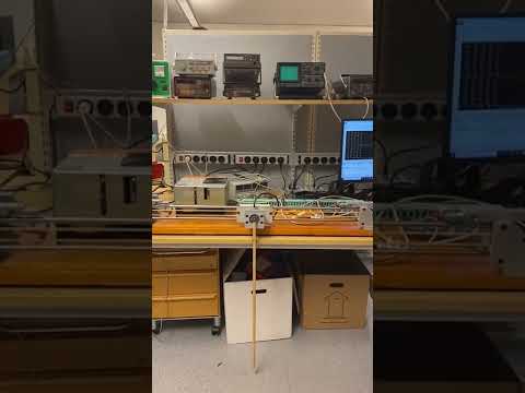
DIY Inverted Pendulum Balancer

Показать описание
I created an inverted pendulum balancing machine, mainly to learn more about PID controllers.
This project took me about 7 weeks to complete, evenings and weekends mostly. It was also a good opportunity to learn more about Atmel AVR microcontrollers.
I use an ATMega8 microcontroller as the core of this design, It has 8 Kb of code space and the project uses about 7.5 Kb.
It uses all three hardware timers (one 16-bit timer and two 8-bit timers), the USART and many interrupt vectors. I think that chip is a great fit for a project like this.
The biggest challenge was not actually balancing the pendulum; it was persuading the carriage not to drift (due to steady state error) off to the left or right and crash into the limit switches.
This was overcome by keeping track of the stepper motor's position by counting the number of steps that had been sent to the motor controller. This x-axis position data was incorporated into the PID control algorithm, to amplify the P, I and D terms when the carriage is away from the centre.
If I use optimal PID tuning parameters, then it simply balances the pendulum; but due to the slight friction in the pendulum's pivot, the pendulum basically just stays there forever, and the system just stops moving. Which is boring, so I loosened the PID parameters a bit and now there is a little bit of chaotic motion in the system that keeps everything just unstable enough to be interesting to sit and watch for a while.
It also is quite resilient to bumps from curious fingers!
2023-05-27
 0:02:47
 0:00:06
 0:01:10
 0:12:44
 0:15:52
 0:00:10
 0:00:18
 0:00:17
 0:21:14
 0:05:38
 0:07:58
 0:13:46
 0:00:33
 0:00:17
 0:02:55
 0:00:24
 0:09:25
 0:00:18
 0:24:50
 0:16:34
 0:00:13
 0:00:27
 0:00:13
 0:00:18