filmov
tv
DIY Programmable Pedal Loop Switcher Build (Part 1)
Показать описание
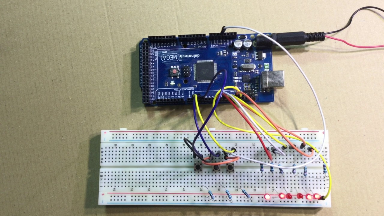
This is part 1 of a True Bypass 8 Loop programmable Loop Switcher that I intend to build. I outline the design and components involved in this video. The 8 Loop Switcher will be built around an Arduino Mega and will require some coding to make it work.
The component list:
225mm x 145mm diecast enclosure
2 x 8 channel relay boards
Arduino Mega
8 x momentary N/O foot switches
18 x 1/4 inch input jacks
power in socket
16 x LED or more
A computer will be required for programming along with a USB cable.
Here is the code thus far that is used in this video.
You can copy and paste from here to Arduino IDE.
/*
Intelligent LOOP SWITCHER for guitar pedal board
by Paul Graham
Note: This sketch is under development and is not complete.
Turns on and off pre-determined relays connected to digital
pin 13,12,11,10,9,8, when pressing a pushbutton attached to pin 2, 3 or 4 for diferent configs.
The circuit description:
* LED attached from pins 13 to 8 with 160 Ohm resistor in series to ground
* pushbuttons attached to pin 2 to 4 from +5V
* 5K resistor attached to pins 2 to 4 from ground
*/
// constants won't change. They're used here to
// set pin numbers:
const int button1 = 2; // button 1 input pin
const int button2 = 3; // button 2 input pin
const int button3 = 4; // bank button input pin
const int loop1 = 13; // loop 1 output pin
const int loop2 = 12; // loop 2 output pin
const int loop3 = 11; // loop 3 output pin
const int loop4 = 10; // loop 4 output pin
const int loop5 = 9; // loop 5 output pin
const int loop6 = 8; // loop6 output pin
// variables will change:
int buttonState1 = 0; // variable for reading button1 status
int buttonState2 = 0; // variable for reading button2 status
int buttonState3 = 0; // variable for reading bankbuttn1 status
void setup() {
// initialize the Loop pins as an outputs:
pinMode(loop1, OUTPUT);
pinMode(loop2, OUTPUT);
pinMode(loop3, OUTPUT);
pinMode(loop4, OUTPUT);
pinMode(loop5, OUTPUT);
pinMode(loop6, OUTPUT);
// initialize the button pins as an inputs:
pinMode(button1, INPUT);
pinMode(button2, INPUT);
pinMode(button3, INPUT);
}
void loop() {
buttonState1 = digitalRead(button1);
if (buttonState1 == HIGH) {
// turn LED on:
digitalWrite(loop1, HIGH);
digitalWrite(loop3, HIGH);
digitalWrite(loop5, HIGH);
digitalWrite(loop2, LOW);
digitalWrite(loop4, LOW);
digitalWrite(loop6, LOW);
}
buttonState2 = digitalRead(button2);
if (buttonState2 == HIGH) {
digitalWrite(loop1, LOW);
digitalWrite(loop3, LOW);
digitalWrite(loop5, LOW);
digitalWrite(loop2, HIGH);
digitalWrite(loop4, HIGH);
digitalWrite(loop6, HIGH);
}
buttonState3 = digitalRead(button3);
if (buttonState3 == HIGH) {
digitalWrite(loop1, HIGH);
digitalWrite(loop2, HIGH);
digitalWrite(loop3, LOW);
digitalWrite(loop4, LOW);
digitalWrite(loop5, HIGH);
digitalWrite(loop6, HIGH);
}
}
 0:10:33
DIY Programmable Pedal Loop Switcher Build (Part 1)
 0:30:12
DIY WIRELESS PEDALBOARD - Programmable Loop Switcher with Arduino 433Mhz!! Part II
 0:22:29
DIY WIRELESS PEDALBOARD - Programmable Loop Switcher with Arduino 433Mhz!!
 0:03:59
How To Make A Guitar Pedal Loop Switcher (And Why You NEED It)
 0:11:30
DIY Programmable Pedal Loop Switcher Build (Part 2)
 0:00:40
DIY Arduino Programmable Switch Looper
 0:04:34
DIY Programmable Pedal Loop Switcher Build (Part 4)
 0:18:11
DIY Programmable Pedal Loop Switcher Build (Part 5)
 0:11:52
DON'T MAKE this CLASSIC pedalboard MISTAKE!
 0:10:28
DIY Programmable Pedal Loop Switcher Build (Part 3)
 0:45:35
DIY 4 Loop Switcher
 0:01:50
DIY Programmable Looper Switcher with LCD Test
 0:01:53
DIY Programmable Looper Switcher Test
 0:05:00
Do I Need A Pedalboard Switching System? What Does It Do?
 0:19:00
How to Build a True Bypass Looper Pedal
 0:03:44
DIY Programmable Arduino FX Loop switcher (SKB Pedalboard mod)
 0:05:23
Building a DIY Effects Loop and Kill Switch!
 0:28:07
DIY True Bypass Loop Switcher Pedal Build ( Two Channel)
 0:11:10
How to make a guitar looper pedal | A fun electronics project
 0:04:11
Hands on with a MIDI-controlled Loop Switcher - Morningstar ML5
 0:00:58
Best Programmable Switcher of 2024
 0:14:55
Patch Cables & Programmable Loop Switcher
 0:00:30
Turning this into a guitar pedal
 0:18:32
building a feedback looper pedal
Комментарии