filmov
tv
Motor start:stop logic with ladder logic | PLC Programming | PLC PROGRAMMING TUTORIAL FOR BEGINNERS

Показать описание
Motor Start/Stop Circuit -
A very useful Ladder Logic Programming Pattern is the Start/Stop Circuit. This pattern is an extension to the Sealed in Coil pattern and is similar to the State Coil. However, where the State Coil is “trigger dominant” (i.e. the Trigger condition takes priority over the Break Condition), the Start/Stop Circuit is “stop dominant”:
Like the Sealed in Coil, the Run coil will always revert to a de-energized (off) state if the PLC is turned off, or if the ladder logic program is reset. That’s a useful property because when starting up the machine we likely want motors, etc., to be in the off state until the logic decides to start them.
The inputs to this circuit are the “Start” and “Stop” conditions. You could imagine both are momentary buttons on an operator screen that are on while the operator is actually pushing the button. If the operator pushes the Start button, then the Run coil will turn on, and it seals itself in until the operator pushes the Stop button. The reason that this pattern is “stop dominant” is that we want the Stop condition to take priority over the Start condition in the case where both signals are active. Imagine a case where the Start condition was stuck on for some reason. At least the operator could stop the motor, etc., by holding the Stop button on until they can turn the machine off with the main switch.
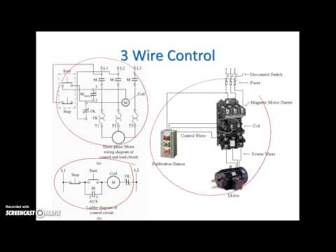
This makes more sense if you imagine that Start and Stop are physical buttons wired into inputs of the PLC. In that case we would normally wire the Start button using a “normally open” contact (so pushing the Start button turns the input on) and we would wire the Stop button using a “normally closed” contact (so pushing the Stop button turns the input off). Normally open contacts can and do get welded in the “on” position sometimes, and making the Stop button take priority over the Start button makes even more sense. In this case, the logic looks slightly different.
The reason the buttons are wired this way is so that if the wire to the Stop button becomes disconnected or power to the Stop button is lost, then the machine will act as if the Stop button has been pressed, and the motor, etc., will stop. This is presumably a safer condition than allowing the motor to continue running without the ability to stop it.
Our Latest PLC-SCADA Video Collection
TON Instruction | Time on Delay | PLC Programming :-
Fundamental of ladder logic | Electrical ladder Diagram
Basic Logic Gates | PLC ladder diagram example
Motor start:stop logic with ladder logic | PLC Programming
Stair Case Logic | Stairs BULB On:Off | PLC programming
Share, Support, Subscribe!!!
A very useful Ladder Logic Programming Pattern is the Start/Stop Circuit. This pattern is an extension to the Sealed in Coil pattern and is similar to the State Coil. However, where the State Coil is “trigger dominant” (i.e. the Trigger condition takes priority over the Break Condition), the Start/Stop Circuit is “stop dominant”:
Like the Sealed in Coil, the Run coil will always revert to a de-energized (off) state if the PLC is turned off, or if the ladder logic program is reset. That’s a useful property because when starting up the machine we likely want motors, etc., to be in the off state until the logic decides to start them.
The inputs to this circuit are the “Start” and “Stop” conditions. You could imagine both are momentary buttons on an operator screen that are on while the operator is actually pushing the button. If the operator pushes the Start button, then the Run coil will turn on, and it seals itself in until the operator pushes the Stop button. The reason that this pattern is “stop dominant” is that we want the Stop condition to take priority over the Start condition in the case where both signals are active. Imagine a case where the Start condition was stuck on for some reason. At least the operator could stop the motor, etc., by holding the Stop button on until they can turn the machine off with the main switch.
This makes more sense if you imagine that Start and Stop are physical buttons wired into inputs of the PLC. In that case we would normally wire the Start button using a “normally open” contact (so pushing the Start button turns the input on) and we would wire the Stop button using a “normally closed” contact (so pushing the Stop button turns the input off). Normally open contacts can and do get welded in the “on” position sometimes, and making the Stop button take priority over the Start button makes even more sense. In this case, the logic looks slightly different.
The reason the buttons are wired this way is so that if the wire to the Stop button becomes disconnected or power to the Stop button is lost, then the machine will act as if the Stop button has been pressed, and the motor, etc., will stop. This is presumably a safer condition than allowing the motor to continue running without the ability to stop it.
Our Latest PLC-SCADA Video Collection
TON Instruction | Time on Delay | PLC Programming :-
Fundamental of ladder logic | Electrical ladder Diagram
Basic Logic Gates | PLC ladder diagram example
Motor start:stop logic with ladder logic | PLC Programming
Stair Case Logic | Stairs BULB On:Off | PLC programming
Share, Support, Subscribe!!!
 0:04:48
Motor Start Stop Ladder logic PLC Programming Tutorials for Beginners
Motor start:stop logic with ladder logic | PLC Programming | PLC PROGRAMMING TUTORIAL FOR BEGINNERS
 0:06:38
Siemens PLC Training: Motor Start and Stop Ladder Logic PLC Program | PLC Programming Examples
 0:01:38
Basic Motor Control - Motor Start Stop Circuit
 0:10:00
PLC Code - START STOP Motor & Pump - Learn Schneider PLC
 0:12:45
Start / Stop Motor Ladder program PLC - Haitham Khattab
 0:05:15
HOW TO MAKE START STOP CONTROL MOTOR IN PLC LADDER LOGIC
 0:11:27
LD 10 - Start Stop Motor Ladder Logic Program - Easy PLC Programming Tutorials for Beginners
 0:14:55
Ladder Diagram Basics #3 (2 Wire & 3 Wire Motor Control Circuit)
 0:00:15
Basic Start Stop Motor control starter #shorts #viral #electrical
 0:03:57
ladder logic program for motor reverse and forward
 0:13:01
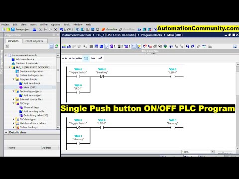
Single Push button ON/OFF PLC Program - Example Problems for Practice
 0:06:46
Direct Motor Starter with PLC | PROGRAMMABLE LOGIC CONTROLLER | LADDER
 0:07:18
Single Push Button ON/OFF Motor PLC Program । Single Push button Ladder Logic diagram.
 0:00:53
Ladder Logic - One Input - Start/Stop
 0:00:09
Motor start program | Ladder #shorts
 0:05:33
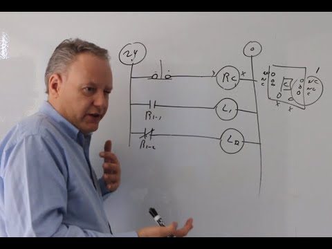
Introduction to Ladder Logic with Relays
 0:13:08
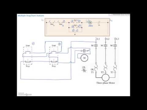
Ladder Diagram Basics #4 (Multiple Stop Start Stations)
 0:00:16
S7 1200 PLC Practical Project
 0:07:43
Basic Motor Control: 3 Wire Start Stop Circuit (updated)
 0:02:01
learn delta PLC programming part-4: Ladder logic to start/stop motor using only one button
 0:23:31
PLC HMI Programming Tutorials for Motors START and STOP based on Time
 0:06:35
PLC Ladder Logic Basics For Beginners With A Working Conveyor
 0:03:38
PLC-based Conveyor Motor Ladder Logic. How PLC is used in a conveyor belt?
Комментарии