filmov
tv
Building the FG085 Arbitrary Function Generator (2/2)
Показать описание
 0:10:39
Building the FG085 Arbitrary Function Generator (1/2)
 0:07:38
Building the FG085 Arbitrary Function Generator (2/2)
 0:01:08
Building The FG085 miniDDS function generator from JYE Tech
 0:08:57
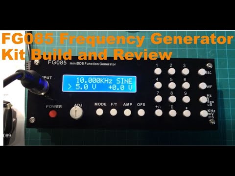
FG085 Frequency Generator Kit Build and Review
 0:12:55
Montagem do KIT Gerador de sinal FG 085
 0:43:14
Building a FG085 Ebay JYE Tech Function Generator Kit
 0:11:15
SS2 JYETech FG085 Function generator kit build Part 1
 0:53:51
FG085 Mini DDS Function Generator Build - Part 1
 0:07:13
FG085 DDS Function Generator Kit From Banggood - Electronic Project
 0:08:34
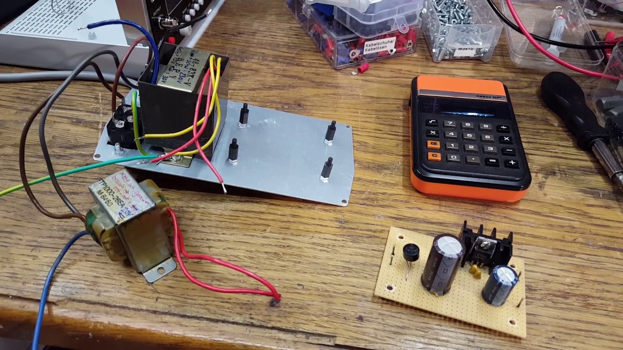
FG085 miniDDS Function Generator Casing and Power Supply Build Pt1
 0:21:56
JYE Tech FG085 Function Generator assembly
 0:03:39
JYETech FG085 demo - Function generator
 0:16:31
FG085 Casing and Power Supply Build Pt2
 0:03:18
FG085 Function Generator review
 0:31:52
FG085 Mini DDS Function Generator Build - Part 2
 0:14:01
Enclosing the FG085 Function Generator- Getting it Right
 0:01:10
Mini gerador DDS - FG085
 0:13:04
FG085 test
 0:21:32
Build An Analog Function Generator
 0:00:25
Broken Sparkfun Frequency Generator Kit - FG085 - KIT-11394
 0:06:36
FG085
 0:17:58
FG085 DDS Доработка функционального генератора.
 0:17:02
Montando el Kit FG085 generador de señal DIY (1/2)
 0:23:04
Function Generator Kit Build & Build & Fix & Test & Bin? - 12v Solar Shed
Комментарии