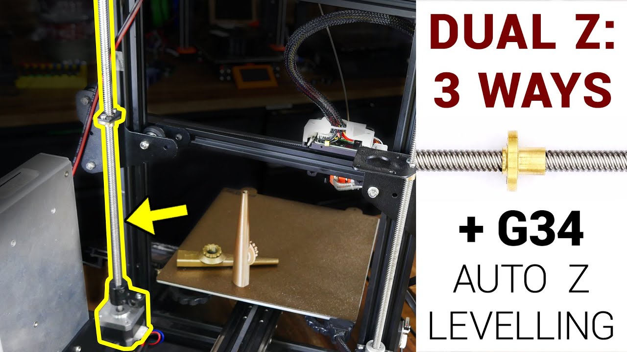
3 ways to add a dual Z axis - Including G34 auto Z levelling

preview_player
Показать описание
A patreon request: make a guide on how to add a second Z axis to an Ender 3. In this video we achieve that, showcasing three methods to get the gantry level. This includes a mechanical belt driven kit from TH3D, adding a 2nd stepper motor in parallel, and a 2nd firmware controlled stepper with G34 auto z levelling.

If you were looking to do this upgrade, hopefully one of these methods will be suitable for you!

Everything in this video was purchased with my own money. The links all point to TH3D for convenience only. 3D printed versions of the concept are linked below.

0:00 Introduction

0:42 Identifying the problem

1:56 Overview of the the three methods

3:06 Ender 3 PSU relocation

4:36 Option 1: Mechanical - belt driven leadscrew

7:48 Alignment

9:39 Option 2: 2nd stepper motor in parallel

12:39 Flexible coupler to remove Z banding

13:09 Option 3: 2nd stepper motor with G34 auto alignment
Purchase the BTT SKR E3 Turbo:

14:37 G34 minimum firmware changes

14:56 G34 default behaviour

16:11 G34 slicer start gcode change

16:28 G34 advanced firmware changes

17:59 Conclusion - You on Kazoo!

Get Quality Resins from 3D Printers Online. 5% off storewide for Teaching Tech subscribers [Code: tech5]

Take a look around and if you like what you see, please subscribe.

Рекомендации по теме
Комментарии
Автор

That ending was totally unexpected 😂. Brilliant.

DavidVegaBR
Автор

A few things if you're trying to make your z axis and prints as perfect as possible:
- don't use the power supply relocation shown in the video. This is hanging loose off the end and will vibrate and cause oscillations which can produce ringing artifacts. There are options on thingiverse that add more structural rigidity. The one in the video can be salvaged by printing and gluing a cube to the underside to support it.
- use the dual independent z motor upgrade (option 3). This is the only way to leave the lead screw loose at the top. You specifically DO NOT want to have the lead screw constrained at the top.

Lead screws are not accurate parts and are not rigid. They are not meant to be constrained at the top. As seen in the video, the 2nd option introduced z banding. The flexible Z coupler did help fix it, but constraining it from the top and bottom will still reduce quality. For that reason you want 2 individual motors and lead screws without clamping at the top.

lllllllllllillllllll
Автор

Hehe that was a fantastic ending. Was very unexpected.

As always, excellent video !!

blackwolfecc
Автор

Pro tip: before starting a major upgrade on your printer, make sure that you have already printed out any parts necessary first.
During my last major upgrade, I had already my printer halfway torn apart before I realized "hey, uhh, didn't I need some printed parts for this mod?"
Or you could use this as the perfect excuse to get another printer! "Honey, I need a printer so that I can finish upgrading my printer..." ;-)

Otakunopodcast
Автор

Michael, thanks for using my design for the power supply relocation; I'm honored!

reprintedD
Автор

Everyone who moves the power supply should be adding a ground wire from the power supply case back to a secure solid mount point on the frame.

mrmaddog
Автор

I added the g34 command to my startup script a few months ago and since then I get a perfect first layer every time, well worth implementing

bigfoot
Автор

you know its getting cold down under when Michael starts wearing a hoodie

Mobile_Dom
Автор

Concerning Option 3. It looks nice but this option has some issue with the following bed leveling in case, that bed ins’t fixed and especialy at Ender3 is aluminum bed thin and “soft”. I suppose that this solution is better for Voron, Vcore and so on. Therefore I redefined G34 command to the #define Mechanical_gantry_calibration and check linearity of the X gantry via top mechanical (printed) limiters. After that X gantry is parallel with the top frame and then I can run G35 for Assisted tramming for bed level.

petrtvarog
Автор

I was a huge fan of option 3 and used it for years but it's very likely that you'll get worse prints than just with a single Z because it's almost guaranteed that one of the Z steppers will skip sometime during the print and BAM now you have a crooked gantry mid-print. Then I saw a printer with option 1 installed and it ran for years without needing any adjustment. Don't overcomplicate things, the best is always the simplest.

IntercourseWithYou
Автор

lol waited for this video for a long time, I already installed my dual z and linear rails on the z a month ago (I went for the belt system) and from the experience I have with the installation, I can say you covered most of the things, but for the linear rails (what you didn't covert in this video) I had problems with aligning the frame, took me 2 months to figure out that both of the aluminum extrusion of the z-axis wasn't parallel to each other and I used alignment tools for the linear rails and they should have been parallel with that tool but the problem in the end was with the frame.
So my tip is if you have issues with getting it to work properly, check the frame if it aligned and parallel to each other (it can be an issue also with v rollers)

Talm
Автор

I have just installed the creality Z axis kit on my Ender 3 V2 ( AU$51.00 from Banggood). This kit is supplied the the power supply mounting bracket for Ender 3 and Pro as well as a connection cable for the single plug on the control board. I have increased the Z stepper motor current to 700mA (I have a E3 mini V2 board and tft 35 E3 Display as I did not like the standalone stepper drivers of the original 4.2.2 board).

billbrown
Автор

Great video as always! Though I would like to add one additional method of adding dual Z, which I really only know as it's how my anycubic i3 mega s came stock. Essentially same as the third method, but rather than using an abl sensor, just using a second endstop microswitch. Thus, equipping the printer to have an endstop on connected for both stepper motors. Has the advantage of being cheaper, but admittedly is a lot more limited than the abl method

jasonking
Автор

wow $70 for the "cheapest" option? I just picked up the parts for the "second" option for $30 on aliexpress....

AndehX
Автор

None of these systems works well primarily because they're all poorly designed. When you're talking z-axis precision it would be nice to have precision better than one layer height.

I've noticed with a belt systems that the lead screws are free to move up and down in the bearing blocks, in other words they're is nothing to prevent Z-axis movement, this might not seem like a lot but it's well over three layer heights on every system I checked.

If you use the belt driven dual axis system then you need to print some collars and thrust washers and place them underneath the top bearing blocks. You need to adjust these for minimal backlash. This will reduce z-axis deviation error to less than about 0.1mm

G34 is a joke, you can't possibly be trying to level the gantry by using the bed as a reference point.

Think about what you're doing for a minute, any error in the bed is going to be transferred to the gantry, this means that over time the error will continue to grow and grow and grow until both of them are severely out of plane.

I mean come on the bed is mounted on springs with adjustment screws this is not what you want to use as a reference point.

The proper reference point would be the top of the gantry. Preferably a couple of blocks mounted up there which have been placed accurately using calipers.

Ideally you'd want to take the x-axis gantry to the top and use the two blocks as the reference point to level the gantry.

Some people try to ram the gantry into blocks at the top of the Z-axis under power, this doesn't work. It forces the steppers to skip steps Which introduces quite a bit of error.

I've experimented with the system where they ram the gantry into blocks or into the z-axis and stop at the top and I couldn't achieve any resemblance of precision. And we are talking error rates of plus and minus 0.3mm which is over two layer heights at 0.28 mm

I wouldn't consider two layer heights deviation acceptable by any stretch of the imagination.

The system I use is to manually level the gantry to blocks which have been mounted to the top of the Z-axis

I run the gantry up to the top within 1 mm of the blocks and then I use my fingers on the coupler screws to manually turn them until the gantry makes contact with the reference blocks.

Then I run the gantry back down to the bed..

This is by far the most accurate system I have come up with. I'm seeing precision of 0.003mm

I mean seriously you need the gantry to be square with the frame and use the gantry as a reference to level your bed not the other way around.

dannelson
Автор

Do you recommend two flexible couplers or just on one side? Great video, keep up the good work!

deadSoldier
Автор

7:38 or be a mad man and bolt the spool holder on the tensioner bracket there space in the hole LUL

buder
Автор

Been running the dual-z from a single motor for years now, highly recommend it over the other options, it encourages you to understand where things bind and get everything resolved and properly settled and in-sync/parallel. Nothing can drift out of sync on it's own and I haven't had to level the bed since. Thrust bearings and a shaft clamp keep the smaller threaded rod from popping up into the air, you'll want to fully constrain that instead of relying on gravity.

Roobotics
Автор

What about setting the ounoits for the seconds axis motor? How does the board know where the second z axis motor is? lil confused. Still, an amazing video. Thank you!!

McDeslandes
Автор

So my question is: what does the g34 command do when the bed is unlevel? Does it just make it crooked according to the parallel-ness of the bed?

adamsvette