filmov
tv
How to Wire Discrete DC Sensors to PLC - Part 2

Показать описание
==========================
✅ Check out the full blog post over at
==========================
How to Wire Discrete DC Sensors to PLC - Part 1:
==========================
In this video, you will learn how to wire a 3-wire DC sensor, like an inductive proximity sensor, to a PLC input card.
You will also learn what a 3-Wire Discrete sensor is and recognize some of the common types of 3-Wire Discrete sensors.
DC sensors can be used to indicate the state of a device or a process to the PLC program.
Knowing these input states can allow the PLC program to make decisions, such as, when to start or stop a conveyor motor.
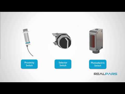
There are many types of discrete 3-wire DC sensors that can be wired to a PLC input.
Some 3-wire devices are NPN or “sinking” sensors, and some are PNP, or “sourcing” sensors. The difference is in how the device operates when the switch actuates.
NPN switches “sink” DC common to the black wire when the switch is activated.
PNP switches “source” 24 Volts DC to the black wire when the switch is activated.
Remember, in both cases, the black wire is connected to the PLC input channel terminal.
For most 3-wire devices, there is typically one brown wire, one blue wire, and one black wire.
A schematic of your specific DC digital PLC input card is required to determine how your specific device should be wired.
For a 3-wire PNP discrete input device, the brown wire will be connected to +24 Volts DC, the blue wire will be connected to DC common, and the black wire will be connected to the PLC digital input channel terminal.
==========================
Missed our most recent videos? Watch them here:
=============================
To stay up to date with our last videos and more lessons, make sure to subscribe to this YouTube channel:
=============================
=============================
#RealPars #DiscreteDCSensor #PLC
 0:13:58
How to Wire Discrete DC Sensors to PLC - Part 1
 0:17:33
How to Wire Discrete DC Sensors to PLC - Part 2
 0:05:44
How to Wire Sensors to a PLC - Part 1
 0:17:33
How to Wire Discrete DC Sensors to PLC Part 2
 0:13:58
3How to Wire Discrete DC Sensors to PLC - Part 1.mp4
 0:16:24
PLC - Wiring inputs
 0:08:50
Sinking and Sourcing PLC Inputs Explained | What is the Difference?
 0:03:28
Wiring Discrete PLC Inputs
 0:02:56
Allen Bradley PLC - Intro to wiring the PLC
 0:08:19
PLC Digital Output Types | Solid State vs Relay
 0:17:15
PLC Discrete Inputs - Control Automation
 0:09:02
what is a PLC. PLC Analog Module Digital Modules. Modular PLC.PLC Input Output modules. Animation
 0:04:31
2 wire - 3 wire - 4 wire Transmitter wiring connections ||Transmitter Power Supply connection detail
 0:07:36
3-wire Inductive Proximity Sensor | How to Read the Datasheet
 0:08:13
Pressure Transducer and Transmitter Wiring Explained
 0:00:56
Arduino Opta: Step-by-Step Guide to Wiring a 24V Discrete Input Sensor
 0:04:03
505 Wiring Connections for Discrete Signals
 0:12:09
Discrete Input module of PLC
 0:13:52
Here is why MOSFET drivers are sometimes essential! || MOSFET Driver Part 1 (Driver, Bootstrapping)
 0:04:48
What are 2-Wire and 4-Wire Transmitter Output Loops?
 0:17:29
How Do Class D Amplifiers Work? - Building A Discrete Class-D Amplifier
 0:06:57
NPN Inductive Proximity sensor. PNP Inductive proximity switch. PNP NPN proximity sensor Animation.
 0:09:10
How to Wire Sensors to a PLC - Part 2
 0:04:03
505XT Wiring Connections for Discrete Signals
Комментарии