filmov
tv
Pressure Transducer and Transmitter Wiring Explained

Показать описание
▶ You can read the full post here
⌚Timestamps:
00:00 - Intro
00:35 - Transducer and transmitter
01:04 - Pressure switch
01:23 - Pressure transmitter
01:41 - Pressure transmitter wiring
02:34 - Wiring pressure switch to PLC
03:51 - Wiring pressure transmitter to PLC
06:07 - Wiring example
=============================
In this video, we’re going to show you how to wire a few different transducers and transmitters to digital and analog PLC input modules.
We’re also going to analyze a typical instrument field-wiring drawing to show you how PLCs are properly configured for different transducer and transmitter types.
A transducer is a device that converts one form of energy to an electrical or electronic signal.
A Pressure switch is a two-part device consisting of a sensing transducer and an electrical switch.
A pressure switch is a digital device because it has only two possible conditions – open or closed. It is therefore connected to a PLC digital input module.
A Pressure Transmitter is a two-part device consisting of a sensing transducer and a circuit that transmits a standard instrumentation electrical signal representing a physical variable being measured. In most applications, the electrical signal is 4 to 20 mA.
A Pressure Transmitter is an analog device and is therefore connected to a PLC analog input module.
Many people refer to this device as a Transducer. For the sake of simplicity, we’ll continue to refer to it as a Transmitter.
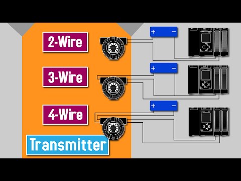
A Pressure Transmitter requires a power supply to operate. Most Pressure Transmitters are two-wire types. Transmitters are also available as four-wire types.
As the name suggests, a two-wire pressure transmitter has only two wires. These two wires provide power for the transmitter and are also the signal lines!
A four-wire transmitter has two wires connected to a power supply and two signal wires connected to the PLC. The power supply can be AC or DC depending on the vendor and model.
1) Digital input – 1756-IF8
We will wire a Gems PS41 series pressure switch to Input 3 of a ControlLogix 1756-IB32 digital input module.
The 1756-IB32 module is capable of supporting up to 32 digital input devices. Each additional device would be wired the same as the Gems pressure switch.
2) Analog input – Single-ended and differential
The analog module can be wired in two possible modes: Single-ended or Differential.
The selection is important as it determines how the module is physically wired.
In Single-Ended mode, we can connect 8 two-wire transmitters sharing one power supply. Each transmitter connection is referred to as a Channel.
2) Analog input – 1756-IF8
The 1756-IF8 module is configured for current input during programming in the I/O configuration.
We will connect the Wika E-11 two-wire transmitter to Channel 5 of a ControlLogix 1756-IF8 analog module.
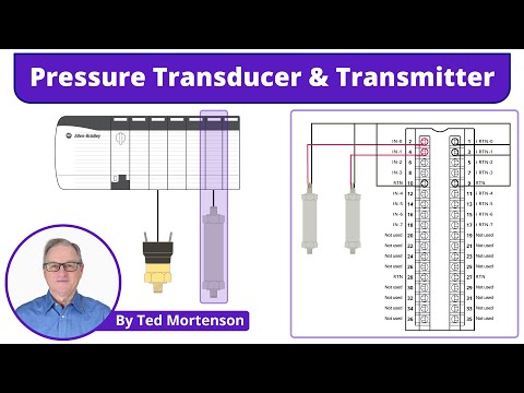
2) Analog input – 1756-IF8 - an industry example
Field wiring diagrams vary between companies. In our example, two channels of the 1756-IF8 are wired in Single-Ended Mode.
We’ll look at how Pressure Transmitter ZT-P3606 is connected to Channel 0, and ZT-P3610 is connected to Channel 1. Both transmitters share the same +24V DC Power Supply.
=============================
=============================
Missed our most recent videos? Watch them here:
=============================
To stay up to date with our last videos, make sure to subscribe to this YouTube channel:
=============================
=============================
#RealPars #Transducer #Industry
 0:08:13
Pressure Transducer and Transmitter Wiring Explained
 0:00:19
PRESSURE TRANSMITTER CIRCUIT DIAGRAM #sensor #transmitter #process #pressure #instruments #engineers
 0:08:26
Pressure Sensor, Transducer, and Transmitter Explained | Application of Each
 0:03:50
How to install and wire pressure transmitter/sensor
 0:00:46
How to Wire Pressure Transducer & Pressure Gauge to VFD #howto #wiring #watersupply #pressurecon...
 0:01:55
How to install a Danfoss pressure transmitter | Walkthrough
 0:07:07
HVAC Pressure Transducer Operation and Testing!
 0:04:31
2 wire - 3 wire - 4 wire Transmitter wiring connections ||Transmitter Power Supply connection detail
 0:02:11
How to wire a Mini DIN Pressure Transducer
 0:03:20
What's the Difference between a Pressure Transducer and Transmitter?
 0:07:44
2-Wire, 3-Wire, and 4-Wire Transmitter
 0:00:16
pressure transmitter wiring diagram #instrument #short
 0:02:11
Wiring the NP400 Pressure Transducer with a DIN Connector
 0:05:33
Pressure Transmitter Explained | Working Principle
 0:02:38
2022 Video Pressure Transducer Installation, Wiring, Maintenance)
 0:00:15
Wika Pressure Transmitter S-10. 0 to 1000 Bar sold out.
 0:06:31
How to connect 2 wire pressure transmitter with PLC ?
 0:00:43
2-Wire Transmitter Connection to PLC #Shorts
 0:00:29
PRESSURE TRANSMITTER 2 WIRE CIRCUIT #electrical #automation #sensor #wiring #circuit #supply #mcb
 0:00:18
What is the difference between pressure Transducer and Pressure switch?
 0:02:08
Franklin P-Series VFD - How to Wire Your Transducer
 0:00:30
RTD Resistance Temperature Detector TT with PLC connection
 0:02:18
WIKA Transmitter vs. Transducer : What’s the Difference?
 0:00:33
CONTROL VFD WITH PID CONTROLLER #VFD #PIDCONTROLLER #transmitter #pressure #acdrive #frequency #hmi
Комментарии