filmov
tv
Finding current through RLC circuit including resistor, inductor and capacitor

Показать описание
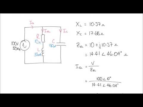
The current through an RLC Circuit including a resistor, inductor and capacitor is found by determining the impedance of the elements, the equivalent impedance of the circuit, and then using Ohm's Law.
Understand: Here, we have a circuit with a sinusoidal input, a resistor, an inductor, and a capacitor. The end goal is to use Ohm’s Law (with complex numbers) to find the current.
Identify Key Information:
• Knowns: We know the rectangular form of the input signal and the resistance, inductance, and capacitance of the components. Additionally, we know the frequency, so we can calculate the angular frequency, 𝜔.
• Unknowns: The polar and phasor form of the source.
• Assumptions: We are looking for the sinusoidal steady state answer.
Plan: Although this problem seems daunting at first, if we can transform to the frequency domain, we can simply use equivalent impedances with Ohm’s Law in the same way we used equivalent resistances with Ohm’s Law in previous lessons. In order to transform to the frequency domain, we have to convert the input signal to phasor form, and then transform the components to
impedances. From there, we can solve for the current using Ohm’s Law and find the rectangular form of the current, is(t).
Solve: First, we convert the input signal to phasor form (ensuring we use the RMS voltage for the magnitude). Recognizing that the frequency of the circuit will not change, we only need to track the amplitude and phase angle; the amplitude and phase can be used to write the output signal in the standard form at the end of the problem:
Ṽ = 169.7 V
∠30∘ = 120𝑉
∠30°
s 𝑅𝑀𝑆
√2
𝑅𝑀𝑆
Next, we find the angular frequency.
𝜔 = 2𝜋𝑓 = 2𝜋(3.18 𝐻𝑧) = 20 radians/s We can use this angular frequency to find the impedances.
ZR = R = 40Ω
𝑍𝐿 = 𝑗𝜔𝐿 = 𝑗(20radians/s)(3𝐻) = 𝑗60Ω
𝑗 𝑗
𝑍𝐶 = − 𝜔𝐶 = − (20radians/s)(1.667 ∗ 10−3F) = −𝑗30Ω
Now, since the components are in series and we have all the values in Ohms, we can simply add them together to get:
𝑍𝑒𝑞 = 𝑍𝑅 + 𝑍𝐿 + 𝑍𝐶 = 40𝛺 + 𝑗60𝛺 – 𝑗30𝛺 = 40𝛺 + 𝑗30𝛺
This leads to the following equivalent circuit:
120V 30o
Now, we can use Ohm’s Law to find the current:
Ĩs =
Ṽ𝑠 Zeq
120VRMS∠30∘
=
(40 + j30)Ω
120VRMS∠30°
=
50Ω∠36.9°
= 2.4Arms∠ − 6.9∘
We can use the magnitude (being sure to convert from RMS value to peak value) and the phase angle of the phasor to convert to rectangular (standard) form of the current. In doing so, we start with the AC equation for current, 𝐼𝑚cos(360°f𝑡 + 𝜙). Then, we set 𝐼𝑚 equal to the RMS value
of the phasor multiplied by √2 and 𝜙 equal to the phase angle of the phasor. Note that the frequency did not change from the source frequency.
𝑖𝑠(𝑡) = (2.4 ∗ √2) cos(360°f𝑡 + 𝜙) A = 3.394 cos(360°(3.18 𝐻𝑧)𝑡 − 6.9∘) A
Answer: The current is 3.394 cos(360°(3.18 𝐻𝑧)𝑡 − 6.9∘) A
Often, when doing analysis on RLC circuits, we want to find the voltage across a specific component – this will be what we refer to as our output voltage. In this case, we can use a voltage divider. To do this, we can use our voltage divider equation, but we replace the “R”s with “Z”s and use the phasor form of the voltage 𝑉𝑡𝑜𝑡𝑎𝑙. Recall that voltage dividers only work with components placed in series, so the impedances must be in series when using a voltage divider.
 0:07:39
 0:10:45
 0:09:27
 0:30:33
 0:06:34
 0:10:38
 0:20:43
 0:37:07
 0:11:56
 0:13:16
 0:12:46
 0:08:41
 0:07:42
 0:11:27
 0:06:41
 0:08:07
 0:02:19
 0:23:06
 0:29:41
 0:00:48
 0:03:57
 0:12:33
 0:02:47
 0:22:26