filmov
tv
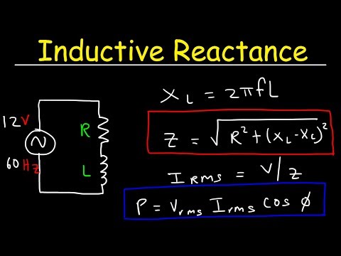
Calculating Series RL Circuit Amps, Ohms, and Volts

Показать описание
Explanation for calculating Impedance, Current, and Voltage Drops when given a resistor and an inductor in series.
 0:12:46
Calculating Series RL Circuit Amps, Ohms, and Volts
 0:14:14
Calculating Power in a Series RL Circuit
 0:22:26
RL Circuits - Inductors & Resistors
 0:12:34
Inductive Reactance, Impedance, & Power Factor - AC Circuits - Physics
 0:06:47
Series RL circuit. Calculating supply voltage.
 0:19:45
Calculating Power Factor and Phase Angle for Series RL Circuits
 0:12:08
Series RLC, Ohms, Amps, & Volts
 0:18:40
35 - Series RL Circuits with Solved Examples | Solving AC Circuit Problems
 0:10:45
Series RLC Circuits, Resonant Frequency, Inductive Reactance & Capacitive Reactance - AC Circuit...
 0:08:08
RL Series Circuit: Calculate Voltages and Currents
 0:09:12
R-L Series Circuit Analysis: Resistance, Inductance, Impedance, and Power Factor Calculation with Ex
 0:14:17
Lab 6 Measurements - RL Circuit
 0:07:42
Find i(t) in RL circuit. | First Order Circuit
 0:09:57
AC series RL circuit
 0:08:24
Series RC Amps, Ohms, & Volts
 0:12:33
Capacitive Reactance, Impedance, Power Factor, AC Circuits, Physics
 0:13:05
RL Series Circuit Analysis: Finding Impedance, Resistance, Inductance & Power in a Series Circui...
 0:11:27
RLC Series Circuit: Impedance, Power Factor, Active Power, & Reactive Power Analysis with AC Sup...
 0:09:53
Simple RL Series Circuit Voltage Calculations Example Problem
 0:08:41
AC Circuits : AC Through Series R-L or L-R Circuit | TheElectricalGuy
 0:02:33
Finding the Source Voltage (Vs) of a Series R-L Circuit
 0:08:54
Series R L circuit Numerical 2: A C Fundamentals : Series AC circuit
 0:00:16
This chapter closes now, for the next one to begin. 🥂✨.#iitbombay #convocation
 0:10:32
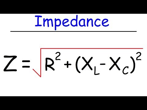
Impedance
Комментарии