filmov
tv
Thevenin's Theorem, Output Impedance, and Input Impedance

Показать описание
How output and input impedance interact
 0:25:39
Thevenin's Theorem, Output Impedance, and Input Impedance
 0:11:20
Thévenin's Theorem: Part 1 Input and Output Impedance
 0:05:21
Input and Output Impedance (Circuits for Beginners #33)
 0:09:12
Thevenin Resistance Example
 0:25:06
Voltage dividers, Input/output Impedance, Thevenin and Norton Equivalent Circuits
 0:09:31
Introduction to Thevenin's Theorem
 0:07:46
Thevenin's theorem Solved Example | Electric Circuits | Network Analysis | Network Theory
 0:00:12
IIT Bombay Lecture Hall | IIT Bombay Motivation | #shorts #ytshorts #iit
 0:07:34
Thevenin Resistance Explained
 0:06:09
Thevenin's Theorem, Inductors, and Capacitors Answer to Question
 0:23:43
Thevenin\'s theorem
 0:09:46
Thevenins Theorem: An Introduction to Thevenin Equivalent Circuits
 0:14:20
AC Electrical Circuit Analysis: Thevenin's Theorem
 0:03:46
Thevenin and Norton Theorem with Examples
 0:46:28
DC Thevenins Theorem (OLD LECTURE)
 0:06:03
Thevenin's Theorem (Circuits for Beginners #28)
 0:15:12
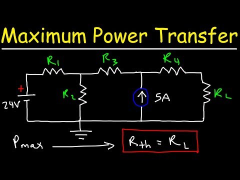
Maximum Power Transfer Theorem Using Nodal Analysis & Thevenin Equivalent Circuits
 0:09:09
Electrical Engineering: Ch 11 AC Circuit Analysis (8 of 55) Thevenin Theorem Example
 0:56:01
008. Circuit Theorems: Superposition, Thévenin, Norton, Source Transformation, Network Equivalence
 0:06:23
Thevenin Equivalent Circuit Solved Example | Electric Circuits | Network Analysis | Network Theory
 0:29:28
AC Thevenin's Theorem (Full Lecture)
 0:04:42
Two Port Network Input Impedance and Thevenin's Equivalent
 0:00:30
1st year to 4th year in my BTECH life ❤️😘😜
 0:21:54
eapbg #28 Norton and Thévenin Theorem
Комментарии