filmov
tv
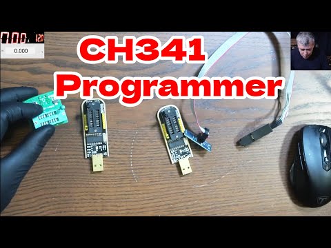
CH341 Programmer 3.3V Fix | Voltlog #318

Показать описание
→Buy CH341A Programmer here
→Support the channel via Patreon, Paypal or Bitcoin
→Blog Post
#VoltLog #CH341 #fixed
Welcome to a new Voltlog, if you watched the previous mailbag video I showed getting this CH341 programmer tool for EEPROMS and FLASH chips and my viewers were quick to point out this actually has a design problem regarding the voltage levels it puts out. So it appears there is a 3.3V regulator on board for providing power to the eeprom or flash chip via the zif socket but the CH341 itself is running at 5V which means it outputs 5V signals on the SPI bus.
Someone has reverse engineered this little board and put together a schematic which clearly shows pin 28 VCC connected to 5V but I want to make sure nothing has changed and this is still present. And checking with a multimeter, pin 28 is still connected to 5V USB. Now I’m just gonna power the programmer from a powerbank and probe the data lines and as we can see they are pulled up to 5V.
Connecting a 3.3V rated part for programming might result in damaging that part. You might get lucky, you might have a chip that will tolerate that but in general that’s bad practice and so we’re going to attempt to fix it by simply cutting the 5V line going into the CH341 pin 28 and supplying it with 3.3V from the onboard regulator instead. And the datasheet also specifies that V3 pin 9 should be connected to VCC and 3.3V as well.
That should be an easy to do job, even without any magnification because the packages used on this board are pretty big but since I have a nice microscope that can also capture full HD images, I’m going to do it under the microscope just so you can see what I’m doing and I’m going to use some enameled copper wire for these mods, this stuff is readily available online, I’ll put a link in the description. So one way to do this mod is to lift pin 28 from the pad, add some insulation between the pin and the pad, maybe some kapton tape and solder a thin wire that will connect pin 28 to 3.3V. Messing with the pcb track bringing in 5V to the chip is risky because we don’t have a board view, we don’t know if that track is connected to something else under the chip so it’s best to leave that alone.
So here is a short clip where I lift pin 28 by first adding in some fresh leaded solder and some flux, then I clean with some IPA and add a thin piece of kapton tape. Next some enameled copper wire was soldered to pin 28 and routed up to the middle pin of the regulator which is the 3.3V rail.
Next I did the same connection for pin 9, but this time there is no need to lift the pin from the PCB because it’s just connected to a bypass cap. To finish this off I would recommend adding some kind of glue to the wires to prevent them from breaking-off. I use some of this transparent silicone adhesive, apart from the fact that it cures pretty slow this is really nice stuff, I highly recommend you get yourself a tube of this and you will find a link in the description below the video
It was a quick 5 minute job to do this mod, really easy and like I said, there is no need for magnification. Now let’s check the voltages we get… and we have 3.3V on pin 28 and on pin 9, that’s good. And let’s check the data pins, yup they are now pulled up to 3.3V which is what we want. So I call this a success and a perfectly good example of the power of the youtube community, oftentimes I’m getting really useful feedback from my viewers and I appreciate that.
 0:06:11
CH341 Programmer 3.3V Fix | Voltlog #318
 0:11:04
CH341A Important 3.3v Voltage FIX - Motherboard BIOS Programmer
 0:18:39
Volt-modding the CH341a Mini Programmer - LFC#278
 0:13:06
How to program a bios chip - CH341A programmer, no, you don't have to modify it
 0:01:27
How To Fix IC not responding error on CH341A PROGRAMMER
 0:11:20
CH341A Programmer MODFIX 5V to 3,3V
 0:05:15
CH341A BIOS Programmer 3.3V MOD - Zer0 2 Infinity
 0:20:35
CH341a v1.6 Review, No More Volt Mods! - LFC#297
 0:02:43
Tutorial Modifikasi Voltase CH341A programmer
 0:19:29
CH341A 3.3VOLT MODIFICATION #MUST HAVE TO PROGRAM BIOS.
 0:13:36
Part - 1 1.8 V 3.3 V Bios Read Write with CH341A. Read Write issue solve. Which bios programmer best
 0:29:18
Using CH341a to recover a mobo I bricked - LFC#279
 0:07:40
How to program | Flash 1.8v bios chip using CH341A
 0:02:24
Error connecting ch341a in windows 10 with ch341a software programmer
 0:14:07
Motherboard with Corrupted BIOS? FIX with CH341A External Flashing Tool
 0:07:54
CH341A mini bios progammer not working.why/how.
 0:36:43
How to reprogram a BIOS flash IC properly with CH341A - The Dos and the Don'ts - Basics #1
 0:11:00
modding the CH341a Mini Programmer 1
 0:00:30
How to Read Hard Drive ROM with CH341A Programmer (Part 1)
 0:10:29
🇬🇧 CH341a – minimal usage guide | how to read & write a motherboard BIOS
 0:10:27
How To Flash Bios Chips or Eeprom Using TVP2588U+
 0:05:18
DON'T USE CH341A until you watch this!
 0:00:16
CH341A to Re-Flash your motherboard for blank screen stuck bios error
 0:00:22
CH341A Mini Programmer reprogramming hp corrupted bios #electronics #repair
Комментарии