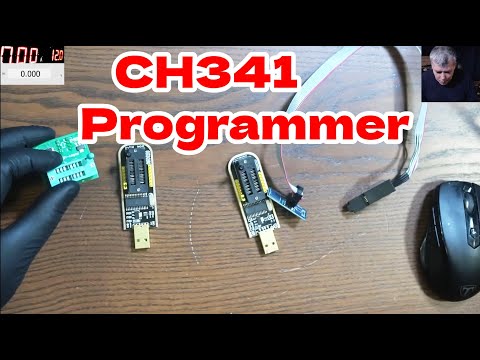
Volt-modding the CH341a Mini Programmer - LFC#278

preview_player
Показать описание

The CH341a Mini Programmer is a super cheap BIOS chip programmer that I've wanted to cover for a while now, but there's a problem with it. While the chip socket is powered at the correct 3.3v, the _data lines_ are pulled up to 5v, which is way too hot. Modifications to run the controller chip off of the 3.3v rail are fairly straight forward, and fix the problem completely.

And the One Transistor article Voltlog referenced:

Рекомендации по теме
Комментарии
Автор

Do not modify this programmer, it's just fine the way it is.
This misinformation was spread about this programmer. It neatly does 3.3 volts and not 5 volts as many claimed. It is now debunked. Do the test yourself, take a flash chip and put it in the zip socket and program, while programming you measure the voltages on the pin. You will now see that 5 volts are not measured anywhere, but 3.3 volts instead. People who understand ohm's law will realize that the wrong measurements were made with no load.

GeertDroid
Автор

all these mods unnecessary . the programmer will adjust itself to 3.3v when programming .I tried it myself and programmed many chips fine . also Sorin proved it he has a video about this matter . not downvoting your video but it is just unnecessary work .

Customer
Автор

Important info for this mod!
The output of the 3V3 regulator is not stable enough to work reliable with all Flash-Chips.
After doing this mod, I was able to read/write multiple chips. But I came across one, that I could read fine, but the CH341 would "crash" aka. disconnect from USB, as soon as I would try to write to it.
As it turned out, I needed to add some capacitance to the output of that 1117 3.3V regulator. In my case, I added a 1µF and another 100nF capacitor right between the 3.3V output and ground (pins 1 and 2 of the regulator). That fixed the issue.
I hope, this comment can save some people from wasting a day debugging this ;)

NebukadV
Автор

"i find it easier to cut the wire to length"
*proceeds to yell at the wire for being too fiddly*

shambleslongplay
Автор

This is honestly the type of video that I like. Technical, detailed and educational...

danielmelendrez
Автор

FYI Apparently this mod is not necessary. Here's another video about it

ctivate
Автор

I love the way you explain things so clearly. I had teachers at school that were so intelligent that they just couldn't put themselves in my shoes and had no way of explaining things without getting too technical. I understood everything here. Cheers dude.

SPEXWISE
Автор

Correct me if I’m wrong..
(And I have been wrong before…)
Yes it’s 5v but there’s less than .5 amp..+-
You’re not going to burn anything with almost no current…
Check it and let me know..🍻

TheBeeman
Автор

What is the point of this tutorial? I have the same programmer and I haven't modified it at all. To rewrite the memories, I use adapters and it's ok (with jumper set to 1-2) What you don't say is that: jumper on 2-3 is for the ISP interface. I use it successfully as USBisp and in Arduino IDE.

toninica
Автор

There is no problem to fix, once you put the chip inside you`ll get 3.3

thegreathitsstation
Автор

It's a big misconception. these do not need to be modified.

retrotech
Автор

Wrong! The data lines are 3.3V when using the device. The voltage on the data lines WITHOUT connection is about 5V but as soon as you connect it to a chip and start communicating the voltage in fact IS 3.3V. So the modification is not only stupid it is also totally useless and even harmfull!

jarnovilen
Автор

Ch341a pin no 28 is vcc 4.5v Minimum to 5.3v Maximum support in this line… i don’t know why you put 3.3v in vcc

JAMSHIDMOBILELAB
Автор

I'm not sure if this would be necessary when the current is less than 1 milliamp.

somber
Автор

Dont need to change anything, when connected to ic, and start program programmmer will adjust Voltage on the pin lines...

cdgcdg
Автор

hello adamantIt YOU ARE MY IDOL !! excellent all your videos thank for you share !!,

One doubt im have macbook pro M1 (year 2020) emc3578 with efi chip model MX25U6472F and have icloud activation lock in case buy the same efi chip and replace maybe working, or if necesary programming anything else.

Thnak you so much for you contribution to community.

julio
Автор

Not gonna lie i could get used to two videos a week.

brslv.
Автор

Hello to all. Actually, there's a much easy way to do this fix; you just have to cut a track on the board and add a plastic jumper on pins labeled '3.3V' and '5V'. I've have successfully flashed a Winbond 25Q64FVSIG which is a 3V chip.

racejay
Автор

This jumper is not necessary actually as the programmer runs 3.3v and has a 3.3v & 5v Jumper on the side so what the jumper actually does is that if you put a jumper, it overrides the 3.3v and makes it 5v remove the jumper and its back to 3.3v. It is located on the side where your CLK, CS, MOSI, MIOS, GND, 3.3V & 5V pins are, just put a jumper on 3.3v & 5v to get 5v.

laptopandcellphonerepairs
Автор

Is there any ch341a programmer that is sold preconfigured to 3.3 volts? I do not have any soldering experience and would prefer to just buy one premodded.

cemsengul