filmov
tv
How to Make a Raspberry Pi Compute Module 4 Carrier Board in KiCad - Part 1 | Digi-Key Electronics
Показать описание
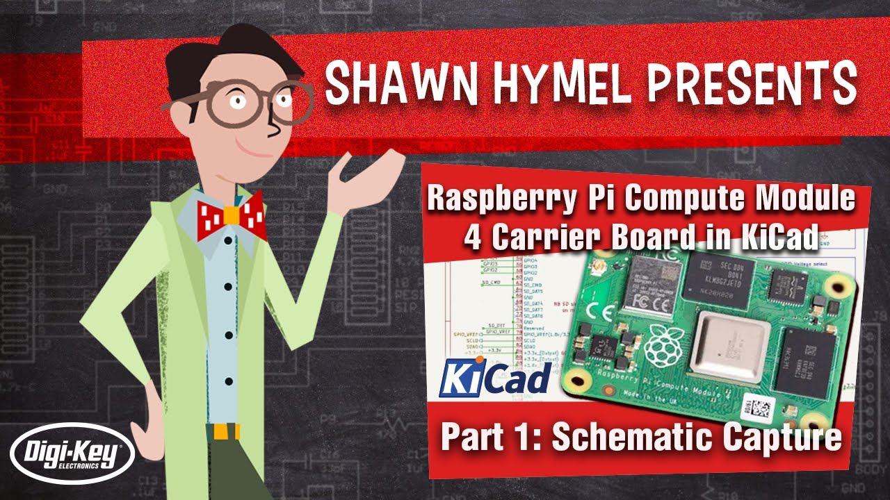
Raspberry Pi released the Compute Module 4 (CM4) in October, which is a single board computer with all of the processing power of the Raspberry Pi 4, but in a tiny form factor! It removes many of the connectors (USB, HDMI, etc.), as the intention is for you to add your own with a custom board and enclosure.
The CM4 is not intended to be a desktop replacement (like the RPi 4) but rather to be used in industrial or professional cases where you might need an SBC embedded in, say, a robot.
In this series, we’ll show you how to create your own, custom Raspberry Pi CM4 carrier board with KiCad!
The video shows you how to work with hierarchical sheets in KiCad and add custom components. You can find pre-made schematic symbols and footprints for some components on Ultra Librarian or SnapEDA.
We add USB-C power, USB 2.0 data (client mode), LEDs, a Qwiic/Stemma connector, and a basic header to the CM4 carrier board. While this particular board has not been tested (yet) when this video was released, we hope that this video helps you create your own carrier board!
Product Links:
Related Videos:
Related Project Links:
Related Articles:
 0:00:56
HOW TO MAKE RASPBERRY MEAD (PART 1)
 0:00:49
The Easiest Way to Make Homemade Raspberry jam from Scratch.- No Pectin or Artificial Flavorings.
 0:04:34
Fresh Raspberry Sauce Recipe - How to Make Fresh Raspberry Coulis - Valentine's Day Special
 0:00:11
Healthy Dessert Idea: Raspberry Popsicles💗 #healthydessert #healthyrecipe #healthyrecipes
 0:04:43
EASIEST Homemade Raspberry Jam Recipe | Small Batch Recipe!
 0:01:04
How to Make Raspberry Puree
 0:00:33
How to make Raspberry White Chocolate Blondies! tutorial #Shorts
 0:00:31
How To Make 5 Minute Raspberry Sauce
 0:01:01
Super soft and fluffy raspberry jam crescent bread shaping @AlyssaJaneCali #shorts #viralvideo
 0:02:15
This Raspberry Lemonade Recipe Will Change Your Life! How To Make Raspberry Lemonade
 0:03:27
Raspberry Oatmeal Squares Recipe | How to Make Raspberry Oatmeal Bars
 0:01:45
2 INGREDIENT RASPBERRY SORBET RECIPE
 0:09:33
How To Grow Raspberry Bushes From Cuttings: Easy and Free@
 0:28:25
Making raspberry perfume
 0:04:55
RASPBERRY CAKE FILLING RECIPE
 0:12:26
Raspberry Shrub - How to Drink Vinegar
 0:03:43
How to make Seedless Raspberry Jam
 0:02:46
HOW TO MAKE RASPBERRY BUTTER
 0:06:17
Delicious Raspberry Muffins Recipe
 0:15:04
How To Make Homemade Raspberry Wine: Time-Tested Recipe!
 0:05:15
Raspberry jam without Pectin | Homemade Raspberry Jam
 0:01:26
Easy Raspberry Jam
 0:08:30
LOW SUGAR Raspberry Jam in 20 MINUTES!
 0:08:45
How To Build A Raspberry Trellis | Keep Your Berries Producing For YEARS!
Комментарии