filmov
tv
RDWorks Learning Lab 114 Can We Dither Greyscale images
Показать описание
If you own a Chinese laser cutter this little series of videos about me learning how to use the free software provided, may solve the problem of trying to learn from a virtually unreadable manual.
I am nothing to do with RD Works, I am not an instructor and I am no expert. This series will document the essential bits of many hours of trial and error
I am nothing to do with RD Works, I am not an instructor and I am no expert. This series will document the essential bits of many hours of trial and error
 0:22:44
RDWorks Learning Lab 114 Can We Dither Greyscale images
 0:31:39
RDWorks Learning Lab 113 What the FACULA is going on
 0:09:27
RDWorks Learning Lab 33 Solar LED edge lit sign
 0:18:25
RDWorks Learning Lab 226 Can my Beam Collimator Work
 0:18:23
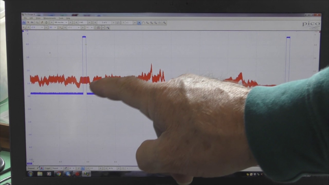
RDWorks Learning Lab 112 Checking those Dots with an Oscilloscope
 0:15:38
RDWorks Learning Lab 80 My Chinese Pizza Oven!!
 0:20:32
RDWorks Learning Lab 120 Strange properties of acrylic
 0:49:45
RDWorks Learning Lab 117 Hunting those Phantom Pixels
 0:43:58
RDWorks Learning Lab 104 Dithered Graphics Not What They Seem
 0:30:04
RDWorks Learning Lab 108 Going Dotty Pt3
 0:33:07
RDWorks Learning Lab 207 The Importance of Beam Intensity
 0:42:57
RDWorks Learning Lab 126 3D Engraving Is this the FINAL Chapter Part 1
 0:55:54
RDWorks Learning Lab 215. AT LAST!!! I understand how lenses cut.
 0:30:42
RDWorks Learning Lab 232 Beam Expansion Means Degraded Cutting
 0:31:21
RDWorks Learning Lab 228 Search for a Beam Collimator Part 1
 0:31:22
RDWorks Learning Lab 106 Going Dotty Part 1
 0:21:54
RDWorks learning Lab 194 I seem to have lost my FOCUS
 0:30:34
RDWorks Learning Lab 224 Blue Dream Begins it's Test work
 0:42:12
RDWorks Learning Lab 247 PWM Grayscale Engraving
 0:21:43
RDWorks Learning Lab 89 Axis Squareness Issue
 0:20:54
RDWorks Learning Lab 69 Rotary Cermarking of glass
 0:40:25
RDWorks Learning Lab 210 Lets Focus on Focus AGAIN
 0:20:03
RDWorks Learning Lab 56 Engraving Pt1 History and Greyscale
 0:47:00
RDWorks Learning Lab 109 Joining the dots Part 4
Комментарии