filmov
tv
Full Wave Rectifiers

Показать описание
This electronics video provides a basic introduction into full wave rectifiers which converts a sine wave AC signal into a pulsating DC signal using two diodes, a load resistor, and a center tap transformer.
How To Solve Diode Circuit Problems:
Diode Logic Gates - OR, NOR, AND, & NAND:
Clipper Circuits:
Clamper Circuits:
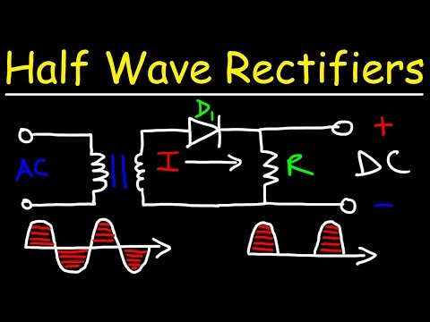
Half-Wave Rectifiers:
__________________________________
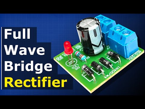
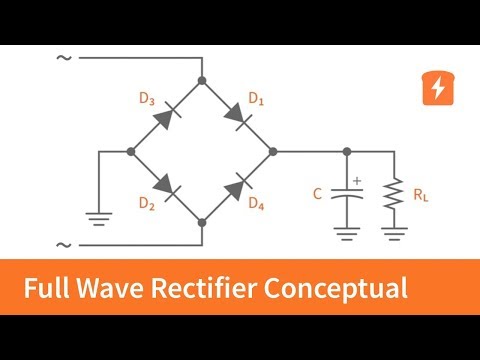
Full-Wave Bridge Rectifiers:
220V AC to 12V DC Converter:
Capacitor Voltage Booster Circuit:
Half Wave Voltage Doubler Circuit:
Full Wave Voltage Doubler Circuit:
__________________________________
Voltage Multiplier Circuit:
Light Emitting Diodes:
Power Dissipation In LEDs & Diodes:
Final Exams and Video Playlists:
Full-Length Videos and Worksheets:
____________________________________
Disclaimer: Some of the links associated with this video may generate affiliate commissions on my behalf. As an amazon associate, I earn from qualifying purchases that you may make through such affiliate links.
How To Solve Diode Circuit Problems:
Diode Logic Gates - OR, NOR, AND, & NAND:
Clipper Circuits:
Clamper Circuits:
Half-Wave Rectifiers:
__________________________________
Full-Wave Bridge Rectifiers:
220V AC to 12V DC Converter:
Capacitor Voltage Booster Circuit:
Half Wave Voltage Doubler Circuit:
Full Wave Voltage Doubler Circuit:
__________________________________
Voltage Multiplier Circuit:
Light Emitting Diodes:
Power Dissipation In LEDs & Diodes:
Final Exams and Video Playlists:
Full-Length Videos and Worksheets:
____________________________________
Disclaimer: Some of the links associated with this video may generate affiliate commissions on my behalf. As an amazon associate, I earn from qualifying purchases that you may make through such affiliate links.
 0:12:29
Full Wave Rectifiers
 0:00:14
Full wave rectifier | Physics | 12th physics | Semiconductor #animation #physics #rectifier
 0:18:59
Full Wave Bridge Rectifier + Capacitor filters + half wave rectifier
 0:04:07
Full Wave Rectifier - Conceptual Review | Basic Electronics
 0:29:02
Full Wave Bridge Rectifiers
 0:00:59
Full Wave Rectifier - Converting AC to DC
 0:08:03
Full wave rectifiers | Class 12 (India) | Physics | Khan Academy
 0:04:05
What is Rectifier | Half Wave Rectifier | Full Wave Rectifier | Electronic Devices & Circuits
 0:00:21
Full Wave Bridge Rectifier + Capacitor filter explanation
 0:18:23
Full wave Rectifier Explained
 0:04:37
How to convert AC to DC | half-wave and full-wave rectifier circuit explained |
 0:05:01
Full Wave Rectifier - Practical Demonstration | Basic Electronics
 0:03:32
Half-Wave vs Full-Wave Rectifiers - Electronics Basics 19
 0:14:05
Half Wave Rectifiers
 0:04:34
Full-wave Center-tapped Rectifier Tutorial | Basic Electronics
 0:08:14
Full Wave Rectifier || End Ch Q 30 || End Ch Q 31 || EDC 2.7(2)(English)(Boylestad)
 0:08:50
Full Wave Rectifier (Basics, Circuit, Working & Waveforms) Explained
 0:00:08
Full wave rectifier with two diodes HIGH #electronics #full #waves #rectifier
 0:13:14
Full Wave Rectifiers with Inductive Loads
 0:20:27
29 Half and Full Wave Rectifier Circuits
 0:28:22
Rectification class 12 | Half wave rectifier | Full wave rectifier | full wave rectification class12
 0:00:05
Half wave rectifier| Full wave rectifier- 📝 #physics #class12 #neet #cbse #jeemains #semiconductor...
 0:08:19
Three-Phase Full-Wave Rectifier Operation
 0:00:09
Difference Between Half Wave And Full Wave Rectifiers
Комментарии