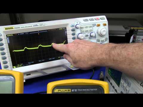
EEVblog #567 - Precision 1A Current Source

preview_player
Показать описание
Dave breadboards a precision 1A current source circuit and finds that even the application reference circuit doesn't work as expected. Showing that you can't just blindly trust that datasheet application circuit will work first go.

EEVblog Main Web Site:
EEVblog Amazon Store:
Donations:
Projects:
Electronics Info Wiki:
Рекомендации по теме
Комментарии
Автор

Any time there is a closed-loop circuit with an emitter-follower directly feeding a low ESR cap, instability or oscillation can result. I have fixed this problem a dozen times, even on production medical equipment. In the old days, 4.7uf ceramic caps didn't exist and electrolytics or tantalums worked fine on any voltage regulator due to their high ESR of 1 ohm or more. Ceramics have very low ESR. and electrolytics had high ESR. It turns out that if the ESR is low enough, many regulators and follower circuits will oscillate. New regulator designs are aware of this. Old part data sheets had to be modified to specify a minimum ESR. Well, you can't guarantee a minimum ESR of a cap, so good luck. For this circuit, try a 1 ohm R in series with the cap.

Spice model a closed-loop op-amp, NPN, and a cap, Then mess with the cap, it's ESR, the load, etc. and see what happens to the step response. Like me, you too will cringe every time you see an emitter follower driving a cap. It has nothing to do with the breadboard. It's just a marginal design that looks OK at first glance.

ericksonengineering
Автор

You forgot to take into account the quantum vector polarization of the electrostatic recombination impedance.

jeremy
Автор

"Amplifiers become Oscillators and Oscillators become Amplifiers" such is the lament of an Analog Design Engineer. Those push-pin type breadboards are notorious for have tons of capacitance between strips. I would build up the prototype on a piece of vector board to eliminate that possibility.

WestCoastMole
Автор

Surprising that you would expect this to work at all on a breadboard. Read the datasheet: the part is extremely sensitive to series resistance in the output capacitor leg, not to mention that the suggested layout is there for a reason.

schwartzenheimer
Автор

You might try baking the LTC6655 overnight at around 100°c. I do it on all surface mount IC's, it seems to stabilize them after soldering.

galileogalilei
Автор

Input and Output directly to ground.. Just ruins your day... Dave, you're a riot! Your videos are informative and entertaining! 7:25 now

edmclaughlin
Автор

I like watching these videos where you go through circuits from theory to practise. I don't understand everything but little by little..

demoguy
Автор

Stick 100pF between base+emitter of pass transistor so high frequency feedback isn't compromised by bandwidth
of the pass transistor?

MarkTillotson
Автор

Your NPN Power transistor has a huge amlification. You get a phase turn beyond 180°: So you need to reduce amplification for high frequencys. This can be done eg, with a RC Pass. I would recommend using a 2 cascaded RC Pass.
Another thing that might produce in a later stage problems is your impedance converter, as it sits in the feedback path. A golden rule for feedback loop is. as short as possible.

mchgartenwohnung
Автор

One way to eliminate any possible noise from the power supply is to use a battery. This is something I have been exploring using the LTC6655 and found it made a notable difference to the noise on the output.

Also breadboards suck for this kind of thing. Parasitic everything, everywhere.

samdenning
Автор

Precision requires a different type of set up a breadboard is no go!

charlesmcboy
Автор

I am an FAE for Linear Technology. the 6655 is a fine reference and there is nothing wrong with the datasheet. I would suggest that one examines the parasitic components associated with a breadboard. Please build the circuit on a perfboard with a plane and then comment on the circuit performance. Think about the plate to plate capacitance inside of that white brick you layed this out on before you disparage the component. I have used it in many instances without a single incident. With the current round of ICs on the market I would contend that the usefulness of the breadboard is nearing its limit,  

rodanone
Автор

Nice, but What about breadboard capacitance?

HowToGuys
Автор

This is the problem with solderless breadboards in general. You're going to get capacitative coupling & lead inductance issues. For precision stuff, you need to go with a dead-bug or custom PCB prototype right from scratch.

theantipope
Автор

Good on, Ive found that you learn more by fails and play about trial and error.
when working for Ekco's in my distant past and working with the old lm741 op amps this was about 1980, you always had to have a cap in the feed back to stop osc.

ronwarren
Автор

Oh, app notes. Always expecting you to have 5 different grounds all on separate planes.

unaliveeveryonenow
Автор

You cant use the ground like this (this IC has two different grounds, check the datasheet block diagram, it would be better if you used the one which controlling the internal reference only and the other one tie it with the circuit ground, it might work). C2 here became a feed forward capacitor as the buffer is not an ideal current source/sink, it should be connected to the real ground in your circuit (and here it will add some delay as your cicuit is a current sense feedback). Another issue, the diode will provide his own feedback with a value related to the current flowing through it (non linear problem). Read about PID  Here is my suggestion: Use instrumentation amplifier, "Inputs" on the sense resistor, its "Output" connected to "Vout_s"; and the gain of the Ins. Amp. can be adjusted for desired current output. And here you can use much lower sensor resistor value (suggested 1 to 100 mohm) :)

salahzayouna
Автор

So the LTC6655 is not 'dead-bug' style.. It's 'squashed-bug' style :)

Great vid Dave

OrbiterElectronics
Автор

How about a cap between the collector and base of the Darlington?

dhpbear
Автор

The amplifier ground does not to have to be on the real ground? outside the diode path?

AllElectronicsGr
join shbcf.ru