filmov
tv
Earth Testing Using Earth Tester | Megger DET4TTD2

Показать описание
Earth Testing Using Earth Tester | Megger DET4TTD2
Working principle of earth probe | Construction
An earth megger is essentially a direct reading ohmmeter with a hand-operated generator that supplies the test current. An ohmmeter essentially consists of two coils (current coil and pressure coil) mounted at a fixed angle to each other on a common axis.
It has four terminals P1, C1, P2, and C2. Its terminals P1 and C1 are short-circuited. This junction makes a common point. So it has three external terminals E (common point), P (P1), and C (C1).
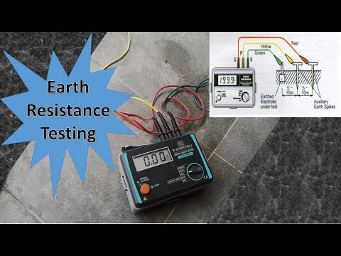
To measure earth resistance with a Megger earth tester, the earth electrode under test is connected to its E terminal and the P and C terminals are connected to the auxiliary electrodes through connecting leads of negligible resistance.
As the handle of the Megger earth tester rotates at a uniform speed, it directly indicates the earth resistance on the dial or calibrated scale. A set of readings is obtained by placing the P electrode at various locations.
First, it can be buried between the earth electrode and the C current electrode. Second, it must be accelerated to a distance of 15 meters from the earth electrode on the side opposite to the current electrode C. The mean of the three readings gives the resistance between the earth electrode and the soil.
The resistance between the earth electrode (ie plates or pipes etc.) and the soil is not constant due to variable moisture conditions. In order to have good and effective earthing, the earthing system should be checked from time to time and the moisture of the nearby soil should be increased by adding water.
#Earth_testing #Megger #Rod
Working principle of earth probe | Construction
An earth megger is essentially a direct reading ohmmeter with a hand-operated generator that supplies the test current. An ohmmeter essentially consists of two coils (current coil and pressure coil) mounted at a fixed angle to each other on a common axis.
It has four terminals P1, C1, P2, and C2. Its terminals P1 and C1 are short-circuited. This junction makes a common point. So it has three external terminals E (common point), P (P1), and C (C1).
To measure earth resistance with a Megger earth tester, the earth electrode under test is connected to its E terminal and the P and C terminals are connected to the auxiliary electrodes through connecting leads of negligible resistance.
As the handle of the Megger earth tester rotates at a uniform speed, it directly indicates the earth resistance on the dial or calibrated scale. A set of readings is obtained by placing the P electrode at various locations.
First, it can be buried between the earth electrode and the C current electrode. Second, it must be accelerated to a distance of 15 meters from the earth electrode on the side opposite to the current electrode C. The mean of the three readings gives the resistance between the earth electrode and the soil.
The resistance between the earth electrode (ie plates or pipes etc.) and the soil is not constant due to variable moisture conditions. In order to have good and effective earthing, the earthing system should be checked from time to time and the moisture of the nearby soil should be increased by adding water.
#Earth_testing #Megger #Rod
 0:14:36
 0:00:52
 0:14:16
 0:02:41
 0:01:51
 0:02:13
 0:05:43
 0:03:28
 0:49:22
 0:00:43
 0:18:10
 0:10:21
 0:04:18
 0:09:55
 0:04:02
 0:02:58
 0:12:55
 0:09:10
 0:04:04
 0:01:03
 0:00:47
 0:07:02
 0:04:54
 0:08:02