filmov
tv
Understanding Timing and Control Unit Design of a Basic Computer | Lesson 18 | Computer Organization

Показать описание
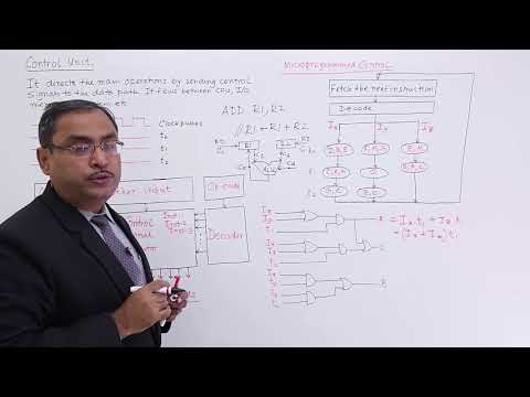
Here we will have Understanding Timing and Control Unit Design of a Basic Computer.
The timing for all registers in the basic computer is controlled by a master clock
generator.
The 4-bit sequence counter can count in binary from 0 through 15. The outputs of the
counter are decoded into 16 timing signals T0 through T15•
The sequence counter SC can be incremented or cleared synchronously
Link for playlists:
 0:12:33
Understanding Timing and Control Unit Design of a Basic Computer | Lesson 18 | Computer Organization
 0:11:59
timing and control in computer organization | COA
 0:16:24
Timing and Control || Design Of Hardwired Control Unit || Computer Organization
 0:04:07
Timing and Control
 0:07:34
Introduction to Control Unit
 0:01:53
Spark Timing & Dwell Control Training Module Trailer
 0:05:24
IGNITION TIMING SIMPLIFIED | The secrets of spark tuning revealed
 0:42:35
Lecture 16: Timing and control unit: Primitive Microprocessor
 0:07:21
Timing and Control / Basic Computer of Control Unit / Control Timing Signals from COA / PRASAD-Sir
 0:05:32
Timing and Control
 0:07:42
Timing And Control | COA | Basic Computer Organisation Architecture | Lec 10
 0:12:06
TIMING & CONTROL UNIT(FULL INFORMATION)| MICROPROCESSOR 8085| INTERNAL ARCHETECTURE OF µP(PART-2...
 0:03:40
TIMING AND CONTROL UNIT OF 8085 MICROPROCESSOR | 8085 ARCHITECTURE
 0:06:18
How Ignition Timing Works: Vacuum and Mechanical Advance Explained!
 0:08:17
2.04 Control Unit of Basic Computer
 0:08:50
Timing and control // control organizations // control unit of basic computers
 0:05:03
Timming and Control | Hindi | COA | Lec-46 | Niharika Panda
 0:01:03
EFI Advanced: Fuel Injection Timing Explained
 0:22:09
Control unit of Basic computer-Timing and control signals
 0:03:53
Car Tech 101: Variable valve timing explained
 0:06:43
Block diagram of Microrpocessor 8085 part II | Timing and Control Unit
 0:18:43
Timing and control unit in 8085 Microprocessor|timing and control unit| address latch enable working
 0:01:30
How CVVT works (Continuously Variable Valve Timing)
 0:06:40
Computer Architecture | Timing and Control | Control Unit of Basic Computer
Комментарии