EEVblog #238 - Power Supply Design Part 7

preview_player
Показать описание
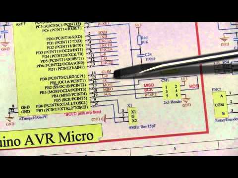
Dave has changed a few things in the Rev B schematic of his power supply design. Talk on opamp specifications, I2C I/O expansion and AVR microcontroller pin usability.
Рекомендации по теме
Комментарии
Автор

@ 00:20 true engineering skill: throw something away and it lands on the desk like someone put it there. :D

PsychoEver
Автор

I first watched this build series back in 2013, and at least once a year, I come back and watch the entire series again. Why? When I feel like I am in a slump, this series reminds me why I started doing this. Attention to detail, on the fly problem solving, and pushing the limits of what can be done on a budget. Still love this series on the PSU. Happy Thanksgiving 2018 from the U.S.A..

thecombatengineer
Автор

I want to thank you very much for encouraging us, teaching us, give us what you know. The words of gratitude that we use in this way are not enough to thank you a thousand thanks¡¡¡¡¡

cearcris
Автор

I don't get why you want to bitbang SPI rather than use the hardware SPI port. The chip specifically handles sharing SPI and ISP because ISP is only active when the chip is in RESET mode. It's quite safe to mix the two on the same pins.

leonerduk
Автор

@exor674 Correct. And it's a good example to show the use of I2C I/O expansion devices.

EEVblog
Автор

@electrodacus A $2 ARM cortex M3 is pointless if you need a DIP package. There are *countless* microcontrollers I could have chosen from a dozen brands, but I didn't, for good reasons.

EEVblog
Автор

@MrP00f So it's available on the I/O connector if required for some other more important task.

EEVblog
Автор

I love it how you use a screwdriver as a pointer! How engineering of you!

(but it still gives me the creeks when it scratches the paper...)

Автор

@keenantims The hardware SPI is now available to the external I/O connector.

EEVblog
Автор

@envisionelec Yeah, that's why I added them. Gives people something new to experiment with too.

EEVblog
Автор

The image in the TLC272 datasheet @22:51 is a copy of the photomask for the metal on the IC (black=metal).  It looks like this chip only has one layer of metal.  Metal connects to the sources and drains of the transistors; polysilicon is used for the transistor gates and short connections underneath the metal.

The pads with notched corners in the LL and LR corners are not bonded out, apparently. (They're probably only used at wafer test--"multiprobe" in TI jargon).  Pin 4 (GND) is bonded to the pad at top center; pin 8 (VDD) is bonded to the pad at bottom center.  Pins/pads are numbered clockwise.

davidthomas
Автор

Very nice revisions and sheet layouts Dave!

I think this is a good project example because you're interfacing I2C, using PWM etc.
and yes, you could use a higher pin-count MCU or a PIC or Vortex 32 but it wouldn't
be something that your average electronics hobbyist would even consider learning a lower level language nor having to buy programming hardware to modify
and experiment with.
Also I think it's keeping more of the 'vibe' with open source.

Nice work again, and thanks for the detail!

philbx
Автор

@logicmindtube Yes, it will be time lapse of some sort, as I have several hours of layout footage captured that I plan to do a voice-over too. No idea how well that's going to turn out though...

EEVblog
Автор

@keenantims Yes, you are right, with hindsight I should have used the bigger device. I missed it. I had used the 8bit one before so was kinda caught up on that and stopped searching. Damn.
The hardware SPI is left free so an Ethernet shield or some other external serial device can use it.

EEVblog
Автор

I cant wait to get one, maybe four. I will build the others for my 3 boys. This will be like Heathkit. Great way to learn Thanks DAVE

fitter
Автор

@jmpattillo I didn't even look into if it was possible on the Ardunio. In any case, some people may want to write their own code.

EEVblog
Автор

@TerminalJack505 Usually the way to go for more pins is to use 74xx595 which is dirt cheap 8-bit serial in, parallel out register with latch, SPI-like input. These I2C exanders have more logic inside, are bidirectional, have interrupt and maybe few more things. Downside is slower I2C access, perhaps not critical in this application. I think Microchip have also the same with SPI bus, it just takes few more pins.

jan.tichavsky
Автор

@21:40 Dave goes on about the odd order of the A, B and C version. It's not A, B and C. It's " ", A, and B. Notice the CD is tacked on the end of all 3 of them. the odd one out at the bottom of the list doesn't have a letter.

jmcorp
Автор

@ahhuhtal
When I remember correctly (did it once), you can still program it, but it will need high voltage programming (rasing the reset line to 12V). This can no longer be done with a standard ISP programmer and the pins you use for programming are then different, too (because many AVRs don't support serial HV programming).

superdau
Автор

@electrodacus You missed the whole point. That's not a DIP part, which I am trying to use. Nor is it Arduino compatible.

EEVblog