filmov
tv
Why there is no Neutral in Transmission Lines? Explained | TheElectricalGuy

Показать описание
Understand why there is no neutral provided in transmission line and why we need neutral in distribution. Electrical interview questions.
===============================================
📌 Join me on Social Media
===============================================
#electricalinterviewquestions #neutralwire
===============================================
📌 Join me on Social Media
===============================================
#electricalinterviewquestions #neutralwire
 0:08:46
Why there is no Neutral in Transmission Lines? Explained | TheElectricalGuy
 0:13:33
Three Phase Mystery Solved, No Neutral Required in a Balanced Load?
 0:02:10
What does the Neutral Wire Do?
 0:23:03
Does Current Flow on the Neutral?
 0:07:54
Can we remove Neutral wire? Importance of Neutral wire
 0:07:36
Can You Get Shocked From a Neutral Conductor?
 0:03:22
Why 240v Circuit Has no Neutral? Know How It Works!
 0:07:41
Does Current Flow Through The Neutral Wire?
 0:01:19
Where does the neutral wire come from, explained
 0:04:00
Why do I need a neutral in every switchbox?
 0:11:13
Ground Neutral and Hot wires explained - electrical engineering grounding ground fault
 0:04:41
why doesn't a 240v circuit need a neutral???
 0:07:19
What Will Happen if Transformer Neutral Supply Brake @TheElectricalGuy
 0:00:21
Why there is no neutral in transmission line?
 0:00:40
There is no neutral ground anymore...
 0:13:08
NEUTRAL CURRENTS IN 3 PHASE SYSTEMS – WHERE DO THEY GO TO – WHY ARE THEY DIFFERENT TO SINGLE PHASE?...
 0:03:05
SHORTS - WHY WE BOND (Neutral & Ground) Explained in 3 Minutes
 0:16:55
There is No Neutral | Michelle Johnson | TEDxWakeForestU
 0:06:13
What is a Neutral? The Difference Between Grounded and Grounding Conductors.
 0:09:31
BROKEN NEUTRAL – HOW TO FIND IT – HOW TO TEST THE CIRCUIT AND THE VOLTAGE READINGS TO BE EXPECTED...
 0:04:24
Why there is no neutral in 3 phase? in tamil
 0:16:22
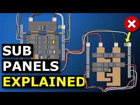
Sub Panels Explained - Why are neutral and ground separated?
 0:05:18
Why voltage not in neutral
 0:00:36
How To Tell A Hot Wire From Neutral When Both Are The Same Color
Комментарии