filmov
tv
TUTORIAL: How to use the ACS712 Hall Effect Current Measure Sensor Module - Arduino (Part 2)

Показать описание
Using the ACS712 current sensor to measure current! With Arduino... This video is about the coding and testing.
 0:00:15
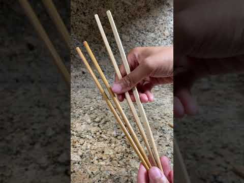
Learn how to hold and use chopsticks 101
 0:00:58
Step by step tutorial for beginners!
 0:01:23
Chopsticks Tutorial 🥢 👩🏫 #learn #culture #tutorial #chopsticks #asian #viral
 0:00:33
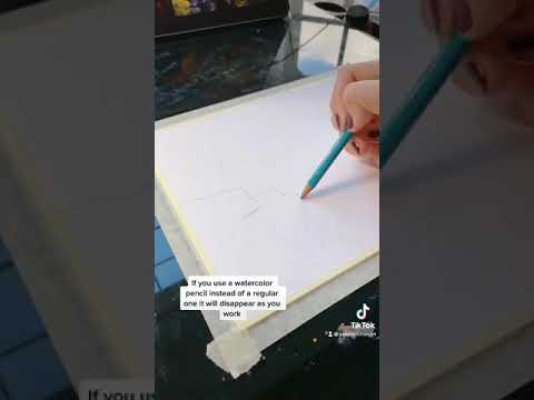
Gouache Tutorial: Let’s Talk Supplies
 0:00:33
Smooth Pull In Transition 💀🔥 | CapCut Tutorial | #shorts #tutorial
 0:10:14
Veo 3 Tutorial - How To Use Googles Veo 3 (Complete Guide)
 0:01:27
TUDOR Tutorial #12: how to use the GMT function?
 0:00:24
Terrain - Unity in 30 seconds
 0:00:24
Learn Move tool in a Simple way. #learnphotoshop #tutorial
 0:01:00
Step By Step Highlight and Contour For Beginners! ✨| #makeupshorts #makeup #makeuptutorial
 0:01:00
4 Beginner Tips For Using Chopsticks
 0:00:26
TUTORIAL: How to animate the world around you!
 0:00:06
Speed Boost Tutorial ⬇️ #fc25
 0:11:35
FL Studio - Complete Beginner Basics Tutorial
 0:00:17
ROTATING CURLING IRON TUTORIAL | vsgbeauty
 0:01:00
How the Minecraft Comparator ACTUALLY Works #Shorts
 0:01:01
How to use a Banana Clip #hairstyle #hairinspiration #fashion #tutorial #explore #explorepage
 0:31:34
How to Use Shopify for Beginners - Crash Course Tutorial
 0:40:08
How To Use The Apple Watch Series 10 - Beginners Guide Tutorial & Tips
 0:16:22
MASTER CANVA IN 15 MINUTES! Canva Tutorial For Beginners
 0:00:13
How to: Properly Use The Peck Deck Chest Fly Machine With Good Form (AVOID THIS MISTAKE)
 0:02:31
Dyson Airwrap™️ Tutorial: How to get started with your Dyson Airwrap™ multi-styler and dryer
 0:10:17
SketchUp Tutorial for Beginners - Learn SketchUp in 10 MINUTES | (SketchUp Free 2022)
 0:00:45
Learn to Sew with a Hemmer Foot! #sew #sewing #sewingforbeginners
Комментарии