filmov
tv
Homemade Wind Tunnel

Показать описание
This is my homemade model wind tunnel that I made for my physics class. The model shows the effects of lift force on different airfoils. See the links below for purchasing materials:
 0:02:25
Desktop Windtunnel
 0:03:57
DIY wind tunnel to visualize the flow lines like Ferrari or Mercedes - Windkanal für Strömungslinien...
 0:06:05
I made a 3D printed Wind Tunnel for my Hot Wheels
 0:09:33
My Homemade Wind Tunnel | High School Project |
 0:04:55
Homemade Wind Tunnel
 0:15:23
DIY Active Aerodynamics | Pt. 1 of 2 - The Wind Tunnel
 0:17:07
Wind Tunnel Build Part 1 (Knowledge Series video 4)
 0:03:17
DIY Wind Tunnel By Michael Funston
 0:01:04
DIY Smoke Tunnel project
 0:00:07
Homemade wind tunnel || Test without vehicle.
 0:05:26
My Mini Wind Tunnel
 0:02:16
F1 Mini Wind Tunnel | Build your own F1 testing facility.
 0:00:16
🥵Hot Wheels Aerodynamics McLaren Speedtail Wind Tunnel Test #shorts #mclaren #aerodynamics
 0:01:30
How to build a homemade wind tunnel?
 0:09:14
Tesla M3 DIY Wind Tunnel Testing - Front End Aerodynamics
 0:00:17
Paper Airplane in Wind Tunnel
 0:11:01
DIY Wind Tunnel!!!(Wind Go weeeeeeeeee) it homemade (obviously)
 0:02:02
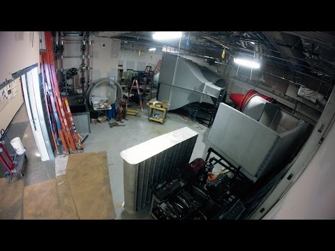
Stanford wind tunnel construction time-lapse
 0:02:55
STRAW - DIY Wind Tunnel Project - by Kap&Kel
 0:00:45
DIY wind tunnel
 0:00:55
Windsible: Desktop Wind Tunnel for Your Diecast Cars Models
 0:01:02
This is the best DIY for an at home wind tunnel just like the children’s museum
 0:00:28
Wind tunnel : Lift Test
 0:03:45
How Wind tunnels Work – Contraction, Test Section, Diffuser, Fan, Turning Vanes and Settling Chamber...
Комментарии