filmov
tv
Arduino Rotary Encoder Circuit Tutorial with Interrupts

Показать описание
A better way for Arduino to read a rotary encoder including programming tips. This uses interrupts.
 0:14:54
Arduino Rotary Encoder Circuit Tutorial with Interrupts
 0:04:55
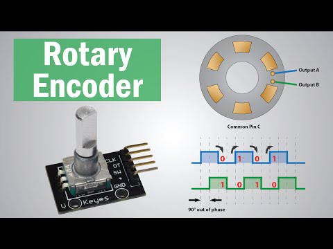
How Rotary Encoder Works and How To Use It with Arduino
 0:10:03
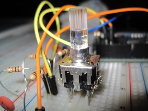
Rotary Encoder with Arduino
 0:32:10
Using Rotary Encoders with Arduino
 0:26:04
Rotary Encoder Tutorial with Arduino Code
 0:00:21
Rotary Encoder With Arduino | Arduino Beginners Tutorial | EP 44 | Learn With Coders Cafe
 0:00:10
Using Rotary Encoder with Arduino | TM1637 LCD Display
 0:14:12
How to use rotary encoders
 0:06:44
Arduino small project, a Pomodo clock with menu
 0:14:44
How to use Rotary Encoder with Arduino
 0:21:11
How to use a Rotary Encoder with an Arduino - CODE EXPLAINED!
 0:00:20
Interfacing Rotary Encoder With Arduino Uno Using ChatGPT Generated Arduino Code | Coders Cafe
 0:05:21
Sunfounder Kit Turorial for Arduino - Rotary Encoder
 0:00:17
Rotary Encoder with Arduino Nano
 0:00:42
Arduino - Rotary encoder Simple Example KY-040
 0:08:21
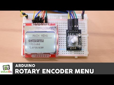
Arduino Menu Tutorial with a Rotary Encoder and a Nokia 5110 LCD display.
 0:17:48
Arduino Rotary Encoder (+ LCD)(4K)
 0:00:53
Cheap 3D Printed Absolute Encoder Knob #Shorts
 0:00:16
Rotary Encoder Beginners Tutorial Arduino #arduino #programming #beginners #tutorial
 0:03:03
ARDUINO Rotary Encoder Controlled Bipolar Stepper Motor with H-bridge tutorial
 0:00:21
Interfacing Rotary Encoder With Arduino Uno Using ChatGPT Generated Arduino Code | Coders Cafe
 0:14:13
How Rotary Encoder Works and How To Use It with Arduino[with CODE] | Arduino Encoder code explained
 0:00:12
Encoder Wiring for Stepper Motor Control #howto #steppermotor #wiring #encoder
 0:00:19
30 Days of Arduino - Rotary Encoder
Комментарии