filmov
tv
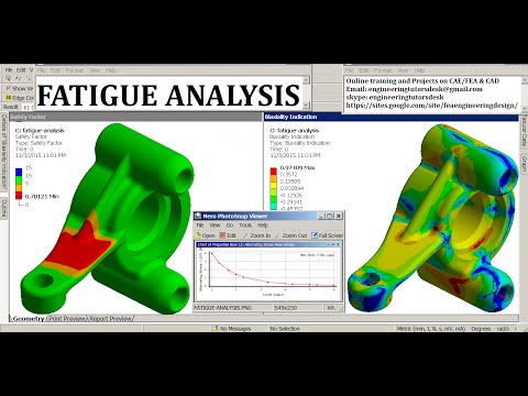
Fatigue Analysis with Multiple Load Sets

Показать описание
Depending on the type of load being applied, you may prefer to group these loads separately rather than put them into a single load set. In addition you may want to analyze certain loads but not others.
In this example, you are working with a gearbox component. In the Model Tree you can see three loads. As is the case with any fatigue analysis, you need to define a material that has a fatigue criteria set. Right-click Material Assignment1 and select Edit Definition to open the Material Assignment dialog box to see what material is assigned. Click More to open the Material dialog box. Under Materials in Model select the material. In this example select GRAY_CAST_IRON and click OK to open the Material Definition dialog box. In the Fatigue area of this dialog box define a Unified Material Law (UML). In the Material Type box, Other, is added to the list of materials. In the Surface Finish box, the list of finishes is updated. When working with a model from an earlier release, a conversion is required. If this is the case, a warning appears indicating that some of the surface finishes defined in the model are no longer supported. You are prompted to provide the Failure Strength Reduction Factor to take these finishes into account. After the materials are defined and applied click OK to close multiple dialog boxes.
The first analysis you need to run is the static analysis. Click Analyses and Studies to open Analyses and Design Studies dialog box. For this example, you can see that the analysis, Gearbox, is completed. Click File ▶ New Fatigue to run a fatigue analysis. In the Fatigue Analysis Definition dialog box there are some changes. The Previous Analysis tab is first, followed by the Load History tab. On the Previous Analysis tab, you can see that the load sets from the model are listed. For this example, select the three load sets and click the Load History tab where you define the Desired Endurance. For this example, Desired Endurance is set to 2e+5. Next, define the load criteria for each load set. In the Load Set box, select the load. Select an Amplitude Type such as Zero-Peak. Complete this operation for each of the load sets in the model. Click OK and then from the Analyses and Design Studies dialog box, run the analysis. After the analysis is completed, you can view the results. In this example you review the fatigue fringe plot for Log Life. In the Results window you can see that most of the model has a Log Life of 20. This means ten to the power of twenty cycles will pass before the crack initiates. You can review the model and see areas that have a lower defined Log Life. To get a better perspective, you can select in the legend and type a value such as 15. This redistributes the levels from first to last so that you can get a better idea of where there are potential issues in the model.
This enhancement improves your ability to analyze a model with multiple loads and to determine the life expectancy of your design.
 0:03:27
Fatigue Analysis with Multiple Load Sets
 0:08:23
Understanding Fatigue Failure and S-N Curves
 0:49:04
Multiaxial Fatigue Life Prediction
 0:10:34
#ABAQUS #Fatigue #analysis #using #DLOAD #subroutine #moving #Load #on #Bridge #Multiple #load #UMAT
 0:17:42
AP07 2 Constant amplitude, non-proportional loading fatigue
 0:55:00
Fatigue Analysis of Offshore Structures
 0:20:07
#ABAQUS_Tutorial | Fatigue Analysis of Spool Shaft with Multiple Block Loading(feat: Fe-Safe)
 0:07:48
Ansys fatigue analysis with Reverse loading & Mean stress theory
 0:01:29
Fatigue Analysis in Altair SimSolid 2020.2
 0:29:01
Fatigue Analysis in ANSYS | Fatigue Failure | HCF High Cycle & LCF Low Cycle Fatigue Life | GRS...
 0:11:35
Fatigue FAILURE CRITERIA in Just Over 10 Minutes!
 0:38:09
Fatigue Analysis in Ansys Workbench | Lesson 36 | Ansys Tutorial
 0:41:21
Introduction to Fatigue Analysis As Per ASME Standards
 0:17:09
Performing Random Vibration Fatigue Analysis Using Ansys Mechanical — Lesson 4
 0:08:40
Fatigue (Strength-Number of Cycles) SN-DIAGRAMS in Under 10 Minutes!
 0:02:53
Fatigue SN Diagrams - Number of Cycles to Fatigue Failure - Example 1
 0:37:48
Fatigue Analysis of Bracket using ANSYS
 0:54:57
Explore Fatigue Essentials and ditch your fatigue analysis spreadsheets
 0:11:03
#ABAQUS_Tutorial (Fe-Safe)| Fatigue Life Estimation of Landing Gear Housing with Fe-Safe(Multi-load)
 0:37:04
Advances in Finite Element Based Vibration Fatigue Analysis
 0:18:52
ANSYS Student: Fatigue Analysis of a Formula SAE Hub
 1:04:41
Stress & Strain life Fatigue with Constant + Fluctuating Load using Ansys nCode
 0:50:12
#12 - Fatigue assessment according ASME VIII Division 2
 0:18:39
Fatigue Curves and Weibull Analysis using nCode GlyphWorks
Комментарии