filmov
tv
Introduction of Ladder Programming In PLC.|| Ladder Programming Of AND,OR,NAND,NOR Gates.

Показать описание
Hello friends in this video you will find the basics of ladder programming and also you will find ladder programming of AND,OR,NAND,NOR gates
#LadderProgramming #LogicGates #MintossMood
#LadderDiagram #ANDGate #ORGate #NANDGate #NORGate
#LadderProgramming #LogicGates #MintossMood
#LadderDiagram #ANDGate #ORGate #NANDGate #NORGate
 0:05:40
Introduction of Ladder Programming In PLC.|| Ladder Programming Of AND,OR,NAND,NOR Gates.
 0:08:19
What is Ladder Logic?
 0:04:45
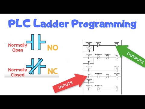
Introduction to PLC Ladder Program: NO and NC Contacts Explained | Automation and PLC Series Part 4
 0:04:26
What is Ladder Programming || Learn Ladder Programming ? || PLC Programming || ladder diagram
 0:03:18
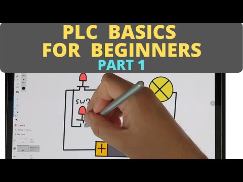
PLC Basics for Beginners - [Part 1]
 0:05:33
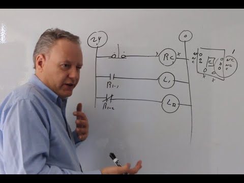
Introduction to Ladder Logic with Relays
 0:01:37
What is Ladder Logic? || An Introduction || PLC Programming Tutorials for Beginners
 0:07:39
Introduction to Ladder Logic Programming (What is ladder logic, WHY IS SO Popular?)
 0:06:35
PLC Ladder Logic Basics For Beginners With A Working Conveyor
 0:00:59
What is Ladder Logic? || An Introduction || PLC Programming Tutorials for Beginners
 0:01:39
What is a PLC? (90 sec)
 0:02:44
Should You Learn Ladder Logic? ABSOLUTELY NOT! PLCs are Obsolete
 0:05:57
Ladder Logic Programming Tutorial For Beginners | Part 1: Basic PLC Instructions | PLC Academy
 0:07:47
OpenPLC - Basic PLC Ladder Programming Example
 0:10:53
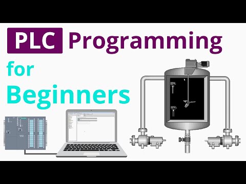
PLC Programming Tutorial for Beginners_ Part 1
 0:15:11
Programable Logic Controller Basics Explained - automation engineering
 0:36:05
Basic Ladder Logic (Full Lecture)
 0:02:35
The History of Ladder Logic
 0:00:16
Programming PLC
 0:00:16
S7 1200 PLC Practical Project
 0:03:48
PLC Programming Tutorials for Beginners || Ladder logic for pusher
 0:11:16
Ladder Logic Examples - PLC Programming Example for Practice
 0:00:57
Best way to learn PLC programming
 0:07:27
What is the Difference between Ladder Logic and Function Block Diagrams?
Комментарии