filmov
tv
How to test a cam sensor with a voltmeter

Показать описание
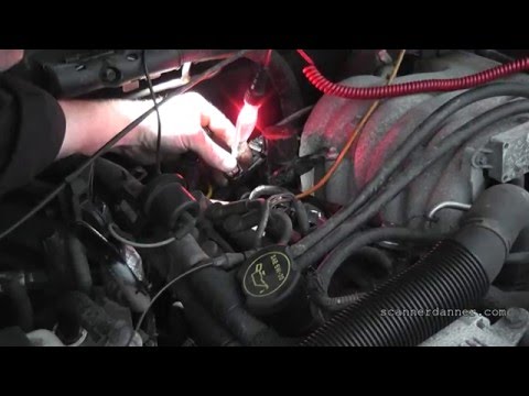
The tests shown in this video apply to camshaft, crankshaft and vehicle speed sensors on ALL Chrysler models, in all production years. The vehicle being tested is a 1997 Jeep with a 4.0L engine.
Chrysler has changed very little in regards to their hall effect sensors throughout the years. Older systems used an 8-9v reference circuit (power supply), where the newer systems use 5v. And with all of them, the signal circuit is a 5v pull-down design.
Engine Performance Diagnostics chapter 21 pages 20-29
Tests shown
- how to check a cam sensor with a voltmeter
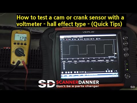
- what does an on/off digital signal look like on a voltmeter
- how to check the 5v reference and ground to the sensor
- how to perform a bypass test
- how to verify signal circuit integrity
Tools used
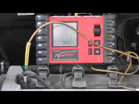
- digital multimeter
- jumper wire
- backprobing pins
- incandescent test light
- scan tool
Related videos
- 1997 Dodge Neon no start, crank sensor problems
- How to test a crank sensor (Chrysler Dodge Jeep)
- How to test a crank sensor with a voltmeter (All Chrysler models)
- 2003 Chrysler-Dodge 3 8L No Start (faulty crank sensor)
Playlist
(Chapter 21) Ignition inputs, cam and crank
On ScannerDanner Premium I will bring you right into my classroom at Rosedale Technical College. You will find page for page lectures taken right from my book as well as exclusive classroom type case studies. What is so special about these classroom case studies? I pull live problem vehicles directly into my classroom and we troubleshoot them in real time, using and applying the theory and testing procedures we learn during the classroom lectures. There is no better on-line training of how to troubleshoot automotive electrical and electronics systems anywhere!
Disclaimer:
Due to factors beyond the control of ScannerDanner LLC, it cannot guarantee against unauthorized modifications of this information, or improper use of this information. ScannerDanner LLC assumes no liability for property damage or injury incurred as a result of any of the information contained in this video. ScannerDanner LLC recommends safe practices when working with power tools, automotive lifts, lifting tools, jack stands, electrical equipment, blunt instruments, chemicals, lubricants, or any other tools or equipment seen or implied in this video. Due to factors beyond the control of ScannerDanner LLC, no information contained in this video shall create any express or implied warranty or guarantee of any particular result. Any injury, damage or loss that may result from improper use of these tools, equipment, or the information contained in this video is the sole responsibility of the user and not ScannerDanner LLC.
Chrysler has changed very little in regards to their hall effect sensors throughout the years. Older systems used an 8-9v reference circuit (power supply), where the newer systems use 5v. And with all of them, the signal circuit is a 5v pull-down design.
Engine Performance Diagnostics chapter 21 pages 20-29
Tests shown
- how to check a cam sensor with a voltmeter
- what does an on/off digital signal look like on a voltmeter
- how to check the 5v reference and ground to the sensor
- how to perform a bypass test
- how to verify signal circuit integrity
Tools used
- digital multimeter
- jumper wire
- backprobing pins
- incandescent test light
- scan tool
Related videos
- 1997 Dodge Neon no start, crank sensor problems
- How to test a crank sensor (Chrysler Dodge Jeep)
- How to test a crank sensor with a voltmeter (All Chrysler models)
- 2003 Chrysler-Dodge 3 8L No Start (faulty crank sensor)
Playlist
(Chapter 21) Ignition inputs, cam and crank
On ScannerDanner Premium I will bring you right into my classroom at Rosedale Technical College. You will find page for page lectures taken right from my book as well as exclusive classroom type case studies. What is so special about these classroom case studies? I pull live problem vehicles directly into my classroom and we troubleshoot them in real time, using and applying the theory and testing procedures we learn during the classroom lectures. There is no better on-line training of how to troubleshoot automotive electrical and electronics systems anywhere!
Disclaimer:
Due to factors beyond the control of ScannerDanner LLC, it cannot guarantee against unauthorized modifications of this information, or improper use of this information. ScannerDanner LLC assumes no liability for property damage or injury incurred as a result of any of the information contained in this video. ScannerDanner LLC recommends safe practices when working with power tools, automotive lifts, lifting tools, jack stands, electrical equipment, blunt instruments, chemicals, lubricants, or any other tools or equipment seen or implied in this video. Due to factors beyond the control of ScannerDanner LLC, no information contained in this video shall create any express or implied warranty or guarantee of any particular result. Any injury, damage or loss that may result from improper use of these tools, equipment, or the information contained in this video is the sole responsibility of the user and not ScannerDanner LLC.
 0:09:58
How to test a cam or crank sensor with a voltmeter - hall effect type - (Quick Tips)
 0:04:32
How to Bench Test Cam, Crank, Speed sensor (Hall effect type)
 0:06:10
How to test a cam sensor with a voltmeter
 0:02:40
Testing the Cam and crank sensors
 0:11:27
Testing a bad cam sensor
 0:00:36
Double weight testing a cam
 0:15:48
Ford Cam Sensor Synchronizer Test
 0:12:18
How to Catch an Intermittent Bad Cam or Crank Sensor
 0:26:01
SELF-DRIVE TOURS IN THE USA IELTS Listening # Cambridge 10 test 1 Listening
 0:14:28
Testing CAM-CRANK Sensor Relationship on a Picoscope
 0:22:47
Hall effect cam/crank sensor operation and testing Part 1 (an SD Premium video)
 0:11:02
LSA CAM TEST-108 vs 112 vs 120
 0:06:13
Effects of Cam Timing on a Big Cam Engine - Dyno tested - 200hp 4AGE
 0:24:06
Hall effect cam/crank sensor operation and testing Part 2 (an SD Premium video)
 0:39:59
How to test cam/crank actuator solenoids (P0010, P0013) 2008 GM 2.4 L
 0:40:52
P0340 Cam Sensor Circuit Code (New Sensor Installed)
 0:02:10
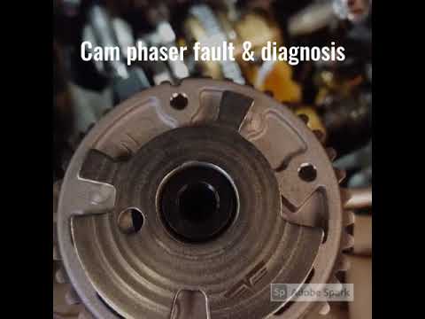
GM 3.6L V6 cam phaser failure & diagnostic
 0:08:37
How to Diagnose Harley Davidson Twin-Cam Cranks With No Spark
 0:11:16
THE ULTIMATE 5.3L CAM TEST VIDEO-HOW MUCH POWER WILL MY CAM MAKE? FOR ANY LS CAM-THE ANSWER IS HERE!
 0:06:21
P0340 or P0344 fix Dodge 3.7L 4.7L 5.7L cam sensor location and testing
 0:12:44
How to fix code P0340. A new cam sensor will not repair this car.
 0:15:58
HOW TO PICK THE RIGHT LS CAM-STOCK vs TRUCK vs PERFORMANCE CAMS (DIY CAMS, DYNO & HOW TO)
 0:45:15
Intermittent stall, no start - P0320, P1391 cam, crank sensor testing (Jeep)
 0:12:33
HOW MUCH POWER IS CAM LIFT WORTH? BTR TRUCK NORRIS VS TRUCK NORRIS NSR LOW LIFT. DOES LIFT MAKE HP?
Комментарии