filmov
tv
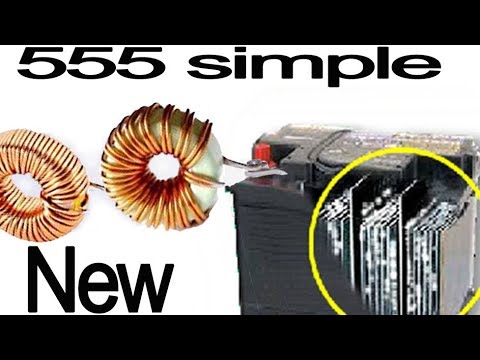
Recover Dead Battery using 555 Timer IC

Показать описание
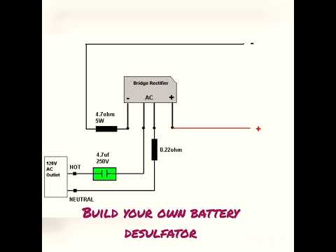
In this video, I will show how to make a battery recovery circuit, This circuit can recover and increase life of lead acid battery.
how to recover dead lead acid battery
how to make battery desulfator circuit
how to desulfate lead acid battery
battery desulfator circuit
Subscribe It's Free ❤️
Circuit Diagram & PCB layout, Gerber Files Download link
Pinterest:
Thanks For Watching
✅LIKE
✅SHARE
✅ COMMENTS
✅ SUBSCRIBE
I hope this video was Useful and you liked it if you did press the thumbs up button.
Creative Techos
#solderingiron #soldering #induction #Electronics #Circuit #Projects
 0:05:04
Recover Dead Battery using 555 Timer IC
 0:06:06
How to make a dead battery work again, simple multi function battery recovery
 0:09:19
How to repair a dead lead acid battery using a can of beer
 0:11:20
DIY Battery Desulfator Battery Restoration Fix Your Own 12v Dead Lead Acid Battery
 0:02:49
Project to recover 100A to 200Ah sulfate battery with 10Khz NE555
 0:07:30
How To Repair Dead 12v Battery With This Circuit
 0:01:00
Car battery repair attempt. Pulse Desulfation. #shorts
 0:09:00
Does An Electronic De-Sulfator Really Repair A Battery?? See Real Results
 0:00:28
dead battery recovery
 0:00:20
DIY LEAD ACID BATTERY DESULFATOR
 0:07:15
How to Desulfate a Lead Acid Battery. #555 Desulfator Circuit modified
 0:00:16
battery positive plates and Acid/battery repair short/local battery/battery plates
 0:04:24
How to desulfate a battery, rejuvenate restore car battery with schematic
 0:01:01
Dead Old Battery Restoration
 0:01:17
Pulse Desulfator , regenerator for Lead-Acid Battery 12 Volt with 555
 0:07:42
Lead Acid Battery Repairing|Recovery Circuit & Guide In Tamil -Desulfator
 0:05:38
How to desulfate a lead acid battery, battery sulfation removal circuit
 0:12:38
How to Recondition your Car 🚗 Battery 🔋
 0:00:16
How to remove 555 IC from circuit board|| Circuit board se IC kaise nikale
 0:00:15
Motherboard repair|computer hanging problems |computer dust problem |computer ko saaf kese Kare
 0:00:48
How To REVIVE A Dead Car BATTERY ► Top Battery Life Extender!
 0:14:17
IC 555 Best to make Auto cut off charger battery DC 12v 8AH to 50AH Full charging
 0:04:18
How to recover a battery using battery desulfator under 17€- 100% Success
 0:00:19
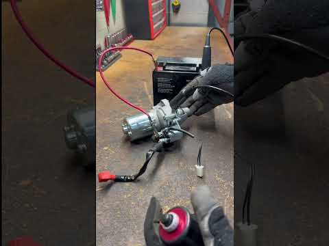
Starter solenoid bypass | Test motor only
Комментарии