filmov
tv
Noise Source and Noise Measurement Basics

Показать описание
Gregory covers the essentials of Noise Sources and Measurements, focusing on the use of a BJT transistor as a noise source. The BJT is configured with a reversed bias at its base-emitter junction, followed by a series of common-emitter amplifiers.
To analyze the noise at the circuit output, Gregory employs a Spectrum Analyzer with a noise marker function. This data is then used to estimate the BJT Excess Noise Ratio (ENR), factoring in the noise floor and amplification gain slope of the measurement setup.
The results are presented as Noise Power Densities and Noise Temperatures, chosen for their convenience in respective calculations. This approach allows for a straightforward yet thorough exploration of the noise characteristics.
BJT PN Junction Noise Source
Video about Noise Temperature and SNR
This video was made possible by Patreon support:
00:42 - Circuit overview
01:32 - Motivation for the measurements
02:54 - Noise characteristics
04:14 - Noise Power Density
05:48 - Reverse-biased base-emitter junction
06:46 - Spectrum analyzer measurement
08:08 - RBW and noise marker
11:24 - Automated measurements
14:54 - Amplifier gain de-embedding
17:10 - Excess noise ratio ENR
19:00 - Spectrum analyzer noise floor correction
23:04 - Circuit description
26:04 - Noise from Zener effect and Avalanche Breakdown
 0:16:20
RF Filter Measurement with Noise Source (How To)
 0:12:29
Measuring Noise Figure using a Spectrum Analyzer - The Gain Method
 0:14:53
Understanding Spectrum Analyzers – Noise Figure
 0:08:19
tinySA and noise source
 0:09:01
What is Noise Figure & How to Measure It – What the RF (S01E05)
 0:04:17
Noise exposure
 0:08:24
Noise Figure Measurement [Y Factor Method]
 0:04:38
Estimation of Equivalent Noise Level
 0:04:50
ACOUSTIC CAMERA & WAVECAM: Vibroacoustics in Mechanical Engineering
 0:02:23
The Basics of Noise - Oscilloscope How To - The 2-Minute Guru (s1e10)
 0:10:52
Electronics tutorial - Filtering unwanted common mode noise from your oscilloscope measurements
 0:37:44
EEVblog #594 - How To Measure Power Supply Ripple & Noise
 0:02:29
Measuring the Output Noise of a DC Power Supply
 0:12:14
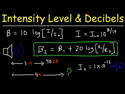
Sound Intensity Level in Decibels & Distance - Physics Problems
 0:12:04
L 11 Noise , Vibration, Harshness, Pass by Noise I Vehicle Testing and Homologation I Automobile
 0:11:40
Noise Figure Measurement [Gain Method]
 0:07:17
Active Noise Cancellation – From Modeling to Real-Time Prototyping
 0:53:29
TSP #162 - Tutorial on Theory, Characterization & Measurement Techniques of Phase Noise
 0:02:45
What is Noise Pollution? | Sources of Noise Pollution | Letstute
 0:07:54
Occupational Noise Exposure - Sound Level Meters
 0:13:39
Resolution, Noise, Dynamic Range | Image Sensing
 0:03:39
Measuring signals buried in noise with an Oscilloscope
 0:07:32
Electronic noise source
 0:04:13
Measuring RMS Noise with an Oscilloscope - by Bob & David
Комментарии