CAN Bus Properties and Troubleshooting

preview_player
Показать описание


Chapters
00:00 Introduction
00:23 What is a CAN Data Bus?
01:00 Components of a Physical CAN Data Bus
01:44 CAN Bus Topology
02:38 CAN Bus Electrical Characteristics
03:07 Oscilloscope View of CAN Bus
04:35 Measuring a CAN Bus with a Multimeter
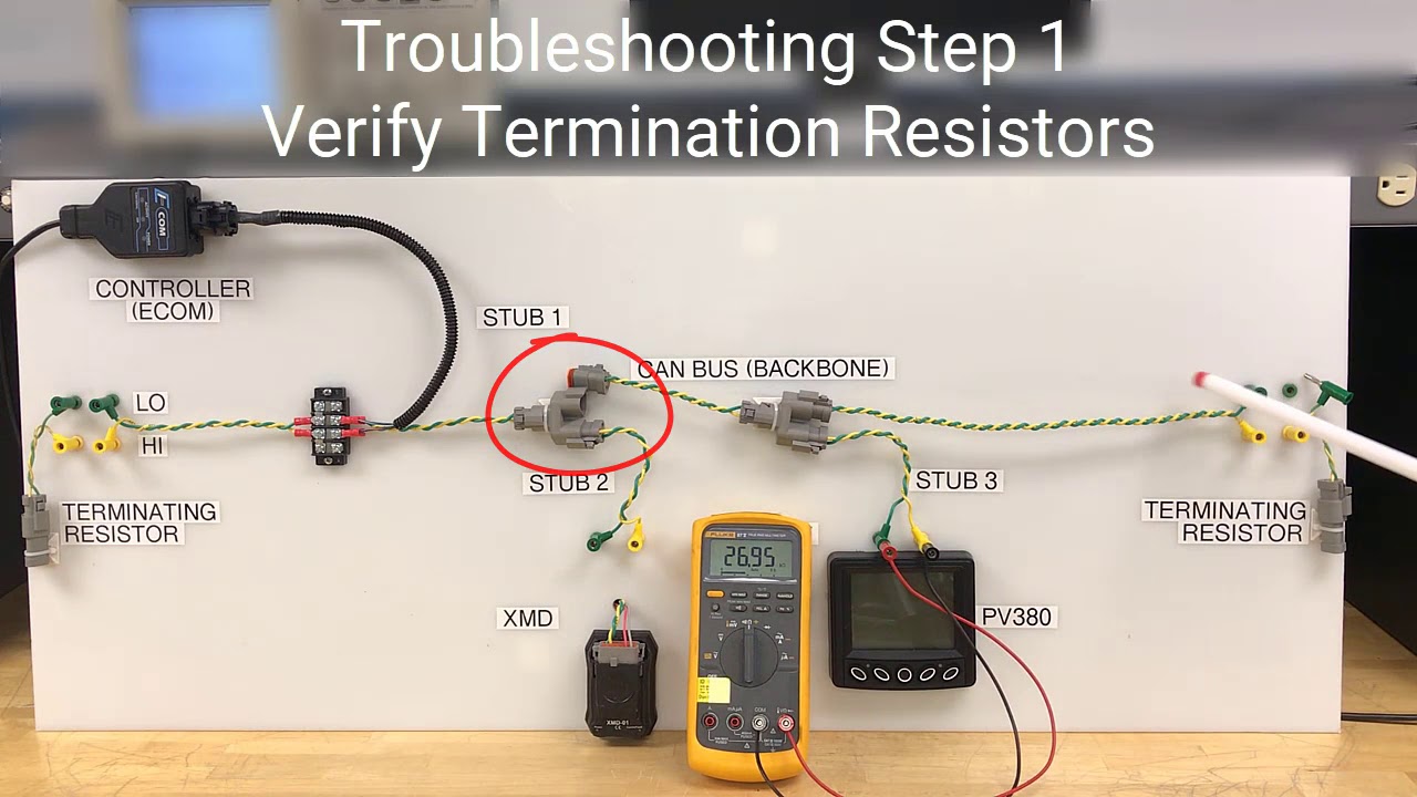
06:34 The Importance of Termination Resistors
08:16 Troubleshooting Step 1: Verifying Termination Resistors
10:23 Troubleshooting Step 2: CAN Hi & Low Wired Backwards
11:59 Troubleshooting Step 3: CAN Signal Missing
12:54 Troubleshooting Step 4: CAN Signal Shorted
17:54 Conclusion
Рекомендации по теме
Комментарии
Автор

Hats off to Enovation Controls for doing what major OEMs would refuse to do because it would hurt their bottom line in service repairs. This is exceptional customer service!

gmracer
Автор

It is much easier to understand when you can see the system as a whole. You are a great teacher. This knowledge is worth more then gold.

blado
Автор

Super demonstration of the CAN Bus system. I'm electronic automobile master technician and most of the content would apply to car and motorcycle as well.
I'n car, the resistance are included in some device such as ECM and cluster or fuse box.

christianouellette
Автор

Theory of operation is always useful, troubleshooting techniques are indispensable . Thanks for giving both, and practical points too for using a DMM as the primary analytical aid.

mineown
Автор

Let me add my voice to the chorus: Thank you! (My interested is automotive) Not to detract from that, there is one thing I think is "missing" and may be confusing to some students. It would be good to run a third wire below the CAN pair showing ground going to all the units, and to which the CAN signals are referenced. ( in fact power might not be bad to show as each of those devices is connected also to power and ground). The problem is that in conventional circuits (non CAN) a pair of wires (particularly a twisted pair) carries one signal, the voltage in one being in respect to the other. In CAN, each wire caries a signal with respect to ground AND also with respect to the other. One signal being the mirror of the other (with respect to 2.5 volts) . While in trouble shooting one looks at the individual signals, each device actually looks at the differential signal. The reason for all this is that it is a very noise immune topography. Noise that gets into one signal also gets into the other, and thus the difference signal is unaffected by noise. BTW, the reason the signal rides on the 2.5 volt carrier is 1) it is tricky in the electronics to handle signals that approach zero (zero crossing issues), and 2) at low and zero volts, no current is carried. The higher the voltage, the higher the current being pulled into the termination resistors. The higher, the current, the greater the signal is with respect to any inducted noise signal. Inducted noise can create high voltages in a high impedance line, but since inducted noise is of low power potential, it produces relatively little voltage in a low impedance line. Thus CAN architecture uses four tricks to overcome noise 1) low impedance transmission (on the backbone), 2) differential signal pair transmission, 3) A base line offset from zero and 4) twisted pair transmission line (decreases inducted noise in the differential signal) .
Thanks again for you excellent tutorial !

petersherrouse
Автор

I kind of understood can bus in automotive field, but this knocked it put of the park. What a great video and explanation for a not so smart guy like me. Thanks!

larrychristopher
Автор

This is the best educational video on CAN bus I've ever seen. Thank you for explaining in such good detail

ryanpeckphoto
Автор

This is great, nice simple introduction to the CAN system for someone like me with long experience of servicing good old fashioned analogue electronics and old simple classic car electrics. And the signal reflection action is probably a bit like what happens when setting up a CB radio rig where you get too much RF reflected back down the cable when the aerial, or antenna, is not properly tuned. And this system reminds me a bit of the digital control systems for model railways where just one power supply can feed all the track but each train, or locomotive will only respond to it's own control commands sent through the same tracks as they each have their own decoder fitted which are all different and only recognise their own codes. But of course even with the CAN system there will still be the age old problems of intermittent connections often caused by corrosion or vibration over time etc. and in my experience with some more modern vehicles I've found that some wiring connectors are ok until they're unplugged and they sometimes start playing up and go intermittent after they're reconnected so I suppose that can happen with this system too, and some more recent vehicles have far too much stuff crammed into too small a vehicle making some wiring well nigh impossible to get at.

majorpygge-phartt
Автор

I've had battle with bad connections on our A&B Devicenet system on a rolling mill. I finally found a good spot in the middle of the loop I can break into and hook up my meter. I use a Fluke with a detachable face and I take the meter face with me and go around to the different components on the loop and lightly give each one a tap and watch the resistance to find the culprit. The Profibus is similar and they use a higher value termination resistors. They use plugs with a D-connectors at the nodes that also have a switch in the plug to switch in or out a termination resistor and sometimes the switch can get dirty and cause problems. I hook up the meter and tap the connectors to find the offensive plug. Your troubleshooting example is spot on. Very good indeed. There is still a lot more for me to learn about these systems.

dandearman
Автор

Great video, exceptionally clear for an introduction to CAN bus. Troubleshooting scenarios were great information for just learning the characteristics of the bus connections vs it’s comms.

WilliamCerniuk
Автор

The troubleshooting shortcuts and wrong impediance is very good. Thank you

satish
Автор

Just wanted to say thank you for the video. Incredibly clear, informative and interesting! I know it was 5 years ago at this point, but please know that it still helps people greatly!

IronMeDen
Автор

Thanks so much for this. I am actually an automotive technician but the principles of CAN are the same in our industry.

radman
Автор

Simply awesome, chased a can bus in a Nissan for weeks because someone cut can-high installing a stereo, wish I had this info then, thank you

Willybill
Автор

SO informative. I knew a lot of this already and I am working with Canbus in the aviation field however this is such a clear explanation it is invaluable.

unclefreddy
Автор

I am new to these systems. This is by far the best explanation I have seen. Thank you so much.

jessehall
Автор

Excellent video, thank you. I have a Marklin Central Station 2 controller unit for my G-Scale model railway which uses a CAN Bus and Gateway to control the trains and various accessories via Decoders, such as points (switches) and signals, model lights, motors, etc. This has really helped me understand how my bus should be setup, and the purpose and use of terminators (snubbers?), and how stubs (track feeders) are used to connect at regular intervals to the centre of electrically isolated sub-sections of railway track, which in so doing also helps to isolate and more easily find bad track connections (caused by weather/corrosion), and reduces bus data reflections. Plus you show how to perform diagnostics on it all. Really VERY useful and well taught. Thanks, Jim

jimprior
Автор

It is all very easy to understand and "trouble shoot/repair" on the demonstration board. The issue is when the circuit is buried in the deepest recesses of the vehicle, inside wiring harness bundles and 20 different modules are on line... and any cut, crimp, or corrosion anywhere in the circuit or any malfunctioning module can disrupt the network. The difficulty is in finding that damaged point in the circuit.

elebeu
Автор

This is what I have been looking for for years, nobody explained it better than this.

wronganswer
Автор

Great teaching and explanation of individual components. Now a "bad kitty" every now and then would be hilarious!

miketaylor
welcome to shbcf.ru