filmov
tv
Using a 16x2 LCD Display with a Raspberry Pi
Показать описание
 0:26:35
Datasheets: 16x2 LCD By Hand (No microcontroller)
 0:09:02
How to Use I2C LCD with Arduino | Very Easy Arduino LCD I2C Tutorial | Arduino 16x2 LCD I2C Tutorial
 0:00:08
Unwrapping a 16x2 LCD Display: What’s inside??🧐🧐 #diy #electronic #arduino #how #arduinoproject #lcd...
 0:12:19
Using a 16x2 LCD Display with a Raspberry Pi
 0:03:37
Raspberry Pi 16x2 LCD Display Python Tutorial
 0:07:43
(16x2) LCD display with Arduino || without I2C module || Simple tutorial
 0:07:31
LCD Basics for the Pi Pico
 0:05:35
16x2 LCD Working principle explained
 0:00:15
Interface 16x2 LCD with Arduino without i2c #shorts #ytshorts #shortvideo
 0:05:21
How to use 16x2 LCD with Arduino || Arduino tutorial
 0:03:30
Using 16x2 LCD Display with Arduino - Tutorial
 0:05:29
How to Set Up and Program an LCD on the Arduino
 0:04:24
How to Control 16x2 LCD Displays With Arduino (Et Discover)
 0:00:16
Interfacing 16x2 LCD Display with Arduino UNO without Potentiometer #shorts
 0:46:23
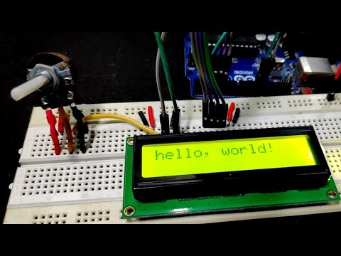
Using LCD Displays with Arduino
 0:05:07
How to use a 1602 i2c Serial LCD Display with Arduino
 0:13:01
How to use a 16x2 LCD Display with Arduino (Parallel interface version)
 0:12:41
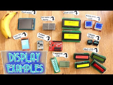
Display examples - which one to use?
 0:06:34
LCD Interface With Arduino UNO || How to connect 16x2 lcd with arduino.
 0:05:22
How to Use a 16x2 LCD Display with Arduino - Complete Tutorial
 0:08:21
How to connect and get a 16x2 LCD Display working with a Raspberry Pi [No external libraries]
 0:17:15
How to Set Up and Program an LCD on the Arduino
 0:00:12
Test LCD 16x2 using I2C with Arduino #arduino #arduinoshorts #shorts
 0:20:02
How to set up and program on the Arduino with 16x2 LCD | Mini Arduino projects
Комментарии