filmov
tv
Arduino Multi Temp Sensor Using NTC Thermistors

Показать описание
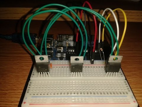
A Thermistor is a component which changes its resistance in relation to the temperature around it. We'll use multiple ones along with regular resistors to measure the temp within the various cells of our new LifePO4 Battery pack to make sure nothing is heating up inside of it.
This uses a simple Arduino Sketch and just these handful of components to measure these localized temperatures quite accurately. If this kind of project is one you are planning yourself, or if you're just interested to see these Thermistors in action, then check out this video.
If you like our video, please do give us a thumbs up as that really encourages us to produce more content like this, and many other topics, as we build our dream robot, one circuit at a time.
 0:16:34
5 temperature sensors for arduino projects
 0:07:11
3 Great Arduino Temperature Sensors // LM34, DS18B20, and DS3231 Real Time Clock
 0:03:47
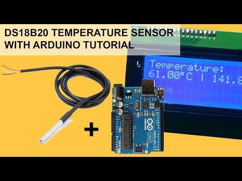
Arduino DS18B20 temperature sensor tutorial
 0:07:01
Interfacing Multiple DS18B20 Temperature Sensor to Arduino/Microcontroller
 0:07:20
Tutorial - Multi-sensor setups for ESP32 & Home Assistant
 0:07:05
Multiple DS18B20 temperature sensors with Arduino
 0:14:20
Arduino Multi Temp Sensor Using NTC Thermistors
 0:02:33
Multiple temperature sensors (Code Included) | Arduino UNO
 0:14:33
Measuring Temperature with a MAX31856, Thermocouple, and Arduino
 0:16:57
Multiple Dallas Temperature Sensor Hook Up & Code
 0:00:27
Make Humidity and Temperature Monitor with Arduino - TM1637 - DHT sensor #arduino #arduinoproject
 0:18:45
Reading multiple DS18B20 temperature sensors using Arduino.
 0:08:32
Multiple Max6675 Arduino, Industrial Temperature Monitor using K type thermocouple & Oled displa...
 0:00:18
Multi temp sensor PT100+NTC MF52+DHT11 with Arduino
 0:05:33
Dallas18B20 Temperature Sensor
 0:00:20
How to Make a Temperature Gauge with Arduino and DS18B20 Sensor 🤯😍
 0:02:46
Connecting many DS18b20 temperature sensors to a single Arduino
 0:12:48
ESP32 - Dual Temperature Sensor (DS18B20)
 0:01:42
Multiple DS18B20 Digital Temperature Sensor to PLC using Arduino, One Wire and Modbus Communication
 0:29:55
Measuring Temperature with Arduino - 5 Sensors
 0:03:53
CONNECT MULTIPLE SENSORS TO ARDUINO | 100 %WORKING | VERY EASY !!!
 0:08:37
How to use DS18B20 Temperature sensor with arduino
 0:09:15
Use Arduino I2C with multiple sensors
 0:01:02
PIC16F690 with Multiple DS18B20 Temperature Sensors
Комментарии