filmov
tv
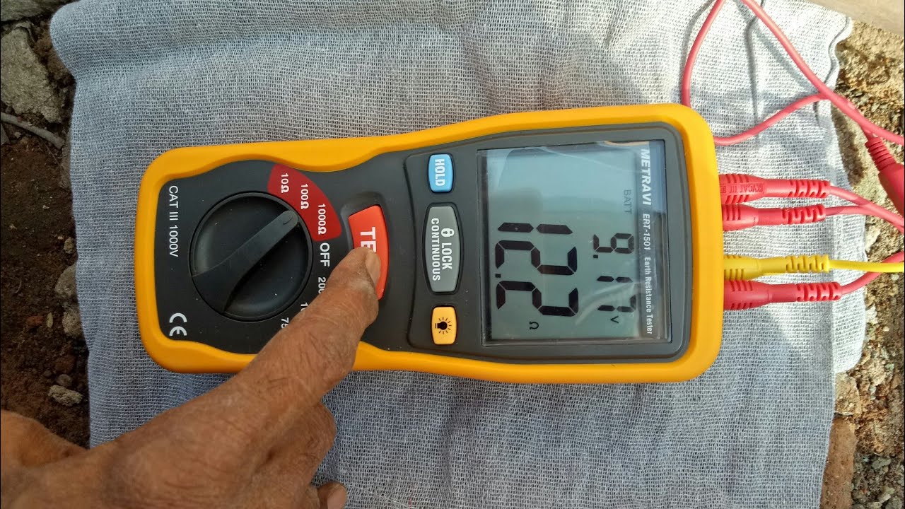
Earth pit resistance testing with Metravi ERT 1501 by FOP method.
Показать описание
Earth pit Resistance checking by Fall of Potential method or 62 percent method using 3 poles Tester:
Connection: Terminals E1 and P1 are shorted and the lead wire is connected to the earth electrode under test. Terminal E2 lead wire is connected to a spike driven at a minimum distance of 10 times the depth of earth electrode. Terminal P2 lead wire is connected to another spike driven at 62 percent of the distance between Earth electrode and E2 spike. The 0 or ref point is always the earth electrode spot for single electrode.
Example : Assume Earth electrode length or buried depth is 1 meter.
Then E2 spike distance is minimum 10 times of earth electrode depth. So the distance is 10 meter away from earth electrode.
P2 spike distance is 62 percent of 10 meter so it is driven at a distance of 6.2 meter away from earth electrode. So P2 spike will be in-between earth electrode and E2.
As far as possible Earth electrode, P2 spike and E2 spike should be in a straight line.
All lead wire size should be minimum 1 sq mm in order to avoid resistance errors.
To get accurate results spike P2 can be shifted 1 meter forward and backward and the readings observed at these 3 spots are averaged. If the resistance value of 3 readings difference is more than 2 ohms then the E2 spike should be moved further ie more than 10 times earth electrode buried depth.
The spike and earth electrode spots can be wetted by pouring water in order to reduce resistance due to dry earth. The depth of the electrode can also be increased to reduce resistance. Another method to reduce resistance is to use multiple electrodes linked together maintaining a minimum distance of twice the depth between each.
 0:04:54
Simple Earth pit resistance test (how to test it) | Earth Tester | Earth resistance Tester
 0:14:16
Earth Electrode Testing
 0:18:10
AEMC® - Understanding Ground Resistance Testing (3640 Discontinued Replaced by 6424)
 0:08:40
How to Test Earth-pit Resistance with Digital Earth Tester
 0:01:31
Earth pit testing||Earth pit testing with Megger||Earth'pit resistance testing procedure
 0:02:11
Earth Resistance Testing of Earthing Pit | Passing Value according to PEC and IEEE ???
 0:11:18
Earth pit resistance testing using Rishabh AET-23 earth tester
 0:05:37
digital earth tester se earth-pit ka resistance test kaise kare || earth-pit resistance test hindi.
 0:03:31
How to check earth pit resistance value using Megger | digital earthing tester |earth value checking
 0:06:49
earth pit resistance test.earth pit testing.earth electrode testing. pipe earthing testing
 0:09:44
Earth pit resistance testing with Metravi ERT 1501 by FOP method.
 0:12:42
Earth pit resistance testing with Kusam Meco KM-2030 tester by FOP method.
 0:09:07
Earth pit resistance testing telugu
 0:02:34
Earth Rod Installation (On site) - Along with Clamps, Connectors, and Earth Pit.
 0:02:04
Ground Rod Explained
 0:02:23
Earth Pit Resistance Test 765KV Substance
 0:04:15
Earth Pit Resistance testing by Motwane Earth Taster
 0:00:58
Earth Pit Resistance Testing with Digital Earth Resistance Tester
 0:03:02
Earth Pit Testing - Earth Electrode Resistance Measure - Earthing Measure - Ground Resistance Test
 0:01:59
How to check Earth Pit resistance using Digital Megger
 0:09:00
Simple Earth pit resistance testing। How to check Earth pit resistance। Earth tester। #earth।...
 0:02:24
How To Measure Earth Pit Resistance Using Earth Tester in Malayalam
 0:04:33
EARTH PIT RESISTANCE CHECKING PROCEDURE - FLUKE 1623 EARTH/GROUND TESTER
 0:03:49
How is calculated Earth Pit resistance - SDI VISAKHAPATNAM
Комментарии