filmov
tv
Basic components #002 - Schmitt Trigger | configurations

Показать описание
We already know how the OpAMP works. But that is not enough. In this video we see why use the Schmitt Trigger Inverter and how to use it. Alos how to create one using the OpAmps from the past video. I hope you ahve learned something new.
------------------COUPONS--------------------
PRINTERS
-------------------------------------
Coupon code: "11CR10EU" or "11CR10US"
Coupon code: "Anete10us"
Coupon code: "Tarantulaus"
COUPON: CR10MINI
Coupon code: "A8KIDA"
------------------LINKS--------------------
Like share and subscribe to motivate me. Thank you
 0:08:57
Basic components #002 - Schmitt Trigger | configurations
 0:00:22
What is Schmitt Trigger Inverter and How It Works in Electronics Circuit
 0:00:12
How A Non Inverting Schmitt Trigger Work in Electronics Circuit
 0:00:06
How to make Schmitt trigger using Transistor
 0:06:47
Electronic Basics #35: Schmitt Trigger and when to use them
 0:03:47
Arduino Interrupts | Schmitt Trigger Debounce Circuit | Salvaging Components
 0:00:17
Discrete Schmitt Trigger Circuit
 0:07:51
Intro to Schmitt Triggers
 0:00:08
Generate Triangle Wave Using Schmitt Trigger Inverter
 0:02:19
Schmitt Components - Solutions in Steel - English
 0:00:10
How to make Inverting Schmitt trigger using OP AMP
 0:00:13
Refining a square wave from an Arduino through a Schmitt Trigger
 0:00:56
Discrete Schmidt Trigger
 0:00:51
Best Electronic Project with BC547 Transistor #shorts
 0:00:13
Non-inverting schmitt trigger Using Op-Amp
 0:00:08
#74LVC1G3157GW, #Schmitt-trigger , #TexasInstruments, #DiodesManufacturers , #TransistorsWholesale
 0:00:08
Schmitt Trigger as Timer
 0:11:00
CD40106BE Schmitt trigger and Inverter
 0:00:15
555 Timer #basicelectronics
 0:04:09
DIY Clip Test Leads | 3D Print Project | Schmitt Trigger Circuit
 0:04:25
Transistor Schmitt Trigger
 0:01:31
MC14584BCP Schmitt Trigger IC , Utsource
 0:07:50
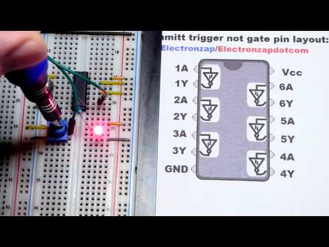
Quick NOT gate 7414 74HC14 hex inverting schmitt trigger integrated circuit IC demonstration
 0:01:00
Schmitt Trigger | Design of Inverting and Non-inverting Schmitt Trigger using Op-Amp | shorts part 4
Комментарии